SVD2 Trigger
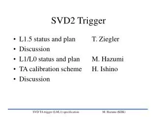
SVD2 Trigger. L1.5 status and plan T. Ziegler Discussion L1/L0 status and plan M. Hazumi TA calibration scheme H. Ishino Discussion. SVD L0 and L1 overview. L0 Latency : less than ~600nsec (in time for VA1TA peaking time)

SVD2 Trigger
E N D
Presentation Transcript
SVD2 Trigger • L1.5 status and plan T. Ziegler • Discussion • L1/L0 status and plan M. Hazumi • TA calibration scheme H. Ishino • Discussion SVD TA trigger (L0/L1) specification M. Hazumi (KEK)
SVD L0 and L1 overview • L0 • Latency : less than ~600nsec (in time for VA1TA peaking time) • Rate : less than 10kHz for increased current (10~20kHz on average now) • Logic : made of ToF, sCDC, VA1TA • Try to keep the logic as simple as possible • L0 should always be fired when L1 hadron trigger is fired • Monitor : Online (DQM) and offline • L1 (CDC-SVD Matching) • Rate : Compensate for the loss of the CDC Z • rate reduction by 30%; 400Hz 300Hz • Logic : Regional matching, output consistent with present L1 logic • Monitor : Online (DQM) and Offline L1.5 will have the larger reduction. Details available at http://belle.kek.jp/~svd2/trigger/TA/doc/ SVD TA trigger (L0/L1) specification M. Hazumi (KEK)
K. Uchida SVD TA trigger (L0/L1) specification M. Hazumi (KEK)
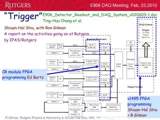
SVD-TA triggerSystem • Terminology • Local L0 System • Tof L0 : TOF Trigger Master • sCDC L0 : • SVD L0 : ADCTF • Global L0 System • Global Decision Logic (GDL or L1) CDC rphi trigger GDL (Global L1) SVD-CDC matching (SVD L1) ADCTF SVD_L0 Global L0 TTM TOF Trigger Board sCDC trigger Monitor TDCs SVD TA trigger (L0/L1) specification M. Hazumi (KEK)
Schedule SVD TA trigger (L0/L1) specification M. Hazumi (KEK)
SVD L0/L1 preparation status • TA tuning study with beta source for z side done • reported at the last SVD meeting • Calibration scheme under testing Ishino-san’s talk • Detailed L0/L1 specification prepared with Iwasaki-san • Most of hardware modules in hand • remaining: OR modules b/w CDC-SVD • monitor boards • Firmware in preparation SVD TA trigger (L0/L1) specification M. Hazumi (KEK)
Tp=75ns <trimDAC> = 2/16 globalTh = 2400e- Result after globalTh tuning Definitions TA hit efficiency = #(w/ TA hits) #(all clusters) for Cluster Energy (CE) >60 ADC counts (~0.5 MIP) TA noise hit fraction= #(w/ TA hist) #(all clusters) for 10 < CE < 40 TA hit efficiency = (87 1)% TA noise hit fraction = ( 3 1)% Threshold curve #(w/ TA hits) #(all clusters) for each bin SVD TA trigger (L0/L1) specification M. Hazumi (KEK)
noise b source all clusters Tp=75ns <trimDAC> = 1 globalTh = 4400e- Result before TA tuning Definitions TA hit efficiency = #(w/ TA hits) #(all clusters) for Cluster Energy (CE) >60 ADC counts (~0.5 MIP) TA noise hit fraction= #(w/ TA hist) #(all clusters) for 10 < CE < 40 TA hit efficiency = (47 1)% TA noise hit fraction = ( 3 1)% w/ TA hits Threshold curve #(w/ TA hits) #(all clusters) for each bin SVD TA trigger (L0/L1) specification M. Hazumi (KEK)
Tp=300ns <trimDAC> = 8/16 globalTh = 4400e- Life is much easier with Tp=300ns ! Definitions TA hit efficiency = #(w/ TA hits) #(all clusters) for Cluster Energy (CE) >60 ADC counts (~0.5 MIP) TA noise hit fraction= #(w/ TA hist) #(all clusters) for 10 < CE < 40 TA hit efficiency = (99 1)% TA noise hit fraction = ( 3 1)% Threshold curve #(w/ TA hits) #(all clusters) for each bin SVD TA trigger (L0/L1) specification M. Hazumi (KEK)
Discussion • Tp=300ns much better than Tp=75ns • Encouraging ! L1 trigger will be OK if we take this option ! • Consistent with IDEAS test results (http://belle.kek.jp/~svd2/va1ta/va1ta_test05.pdf) • L0 latency (max.) = 835ns; Is this acceptable ? • Eff.=87% for Tp=75ns; adequate ? • need simulation study • simple estimation 91.5% for 3-out-of-4 logic • Several possible options • Tp=300ns for Z trigger for L1, Tp=75ns for rphi for L0 • Tp=300ns with L0 latency=835ns • ... • The decision depends on the actual condition. Be flexible for now. • Test_on=0 “seems” more stable SVD TA trigger (L0/L1) specification M. Hazumi (KEK)
L0 Latency detail 450 ns 410ns 405ns 305ns 300ns 240ns ns 355ns 610ns Global L0 (+50) • latest timings are shown • additional delay with pipeline may be introduced ~1m ADCTF (+50) ~1m TOF Trigger Master TTM (+40) (30+2) m *850ns for present L0 sCDC trigger Detector sCDC TOF (30+2) m SVD 90 ns SVD TA trigger (L0/L1) specification M. Hazumi (KEK)
L0 Latency-2 (Tp=300ns) 675 ns 635ns 630ns 530ns 525ns 240ns ns 355ns 835ns Global L0 (+50) • latest timings are shown • additional delay with pipeline may be introduced ~1m ADCTF (+50) ~1m TOF Trigger Master TTM (+40) (30+2) m *850ns for present L0 sCDC trigger Detector sCDC TOF (30+2) m SVD 315 ns SVD TA trigger (L0/L1) specification M. Hazumi (KEK)
C1-3 clk (B4-1) System Block Diagram CDC-L1-rphi-short (64bits) diff. ECL NIM L1 SVDCDC-S C5-2 1+3.5+0.5m LVDS A1-3 NIM LVDS SVD-L0 (36bits) NIM LVDS 10+1m NIM LVDS L1 SVDCDC-L C5-2 C5-1 8 5+1m TOF_L0(1bit) LVDSECL CDC-L1-rphi-long (64bits) B5-1&2 8 to GDL 5+1m L0T (global L0) A1-4 16 1 L0 (to TTM) OR (3216) 64 B3-4 16 8+1m TOF hits(32bits) 16 LVDSECL to monitor TDCs C5-1 (same module) CDC OR (6416) B2-4 CDC OR (6416) sCDC hits(256bits) CDC OR (6416) CDC OR (6416) C3-1 5+1m SVD TA trigger (L0/L1) specification M. Hazumi (KEK)
Module List ordered (delivered) SVD TA trigger (L0/L1) specification M. Hazumi (KEK)
EH floor plan 1 2 3 4 5 6 7 entrance A B C D SVD TA trigger (L0/L1) specification M. Hazumi (KEK)
Schedule SVD TA trigger (L0/L1) specification M. Hazumi (KEK)
Task Sharing • Overall spec. & schedule : Hazumi • Interface to CDC/TOF/GDL : Hazumi • TA study w/ 1/10 : Nakadaira, Hazumi • TA calibration scheme : Ishino, Kaneko • ADCTF trigger firmware : Vienna group • final logic • special firmware for cosmic • L0 firmware : Mikami, Ushiroda • L1 firmware : Hazumi, Kurashiro • TA monitor : Ushiroda, Matsumoto • L0/L1 online software : • L0/L1 offline software : Other potential manpower: Y. Onuki, T. Shibata, M. Watanabe (Niigata), M1 (Tokyo), J. Chen (NTU), K. Hara (Osaka), Y. Nakano, M1 (Tsukuba) SVD TA trigger (L0/L1) specification M. Hazumi (KEK)