Download
1 / 53
610 likes | 1.7k Views
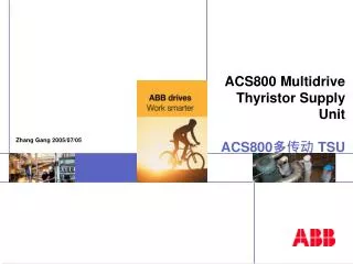
ACS800 Multidrive Thyristor Supply Unit ACS800 多传动 TSU. Zhang Gang 2005/07/05. Common supply modules / TSU. TSU = Thyristor supply unit ( 380 V - 830 V ) From 680 kVA upto 3600 kVA ( 6 pulse ) Two antiparallel bridges (4Q) DC Choke for current smoothing

E N D
ACS800 Multidrive Thyristor Supply UnitACS800多传动TSU Zhang Gang 2005/07/05
Common supply modules / TSU • TSU = Thyristor supply unit ( 380 V - 830 V ) • From 680 kVA upto 3600 kVA ( 6 pulse ) • Two antiparallel bridges (4Q) • DC Choke for current smoothing • Autotransformer for improved line commutation while generating • Microprocessor Control • Software parameters for good functionality and reliability • Independent unit • Auxiliary control by I/O or through fieldbus • Comissioning by panel and/or DriveWindow • Charging of capacitors • Internal protections
Earthing- Switch(Option) Air- Circuit- breaker Reverse Bridge B4 / B5 Forward Bridge B4 / B5 TSU 6-pulse [ B4 / B5 ] / Summary F F F K K K K K A A Choke Trafo400V / 230V
DC Thyristor Supply Unit Thyristor Supply Unit AC 525 kVA 525 kVA TSU B4/B5 晶闸管整流单元 B4 - B5 size
Main Circuit Diagram Of TSU TSU 主回路 3b 3a V13 V15 V11 V24 V26 V22 3~ U d U c 1 2 V14 V16 V12 4 V21 V23 V25 Forward bridge Reverse bridge Intermediate circuit (DC) reactor
TSU – B1~B3 ACU ICU Drive sections Boards 3b 3a I/O 4 Board
TSU – B4/B5 TSU ICU ACU Drive sections 1 2 5 3b 3a Boards I/O Board 4
TSU module in RITTAL TS8 cabinet ACS800 多传动TSU 模块装在RITTAL TS8柜体中
Basic Information 公共供电单元 / TSU基本信息 • TSU = 晶闸管供电单元 ( 380 V - 830 V ) • 从 680 kVA 到 3600 kVA ( 6 脉波 ) • 两个反并联的桥 (4Q) • 直流电抗器,平波作用 • 自耦变压器用于发电时改善线路换向 • 微处理器控制 • 软件参数用于设定复杂功能和提高可靠性 • 独立的单元 • 可以通过 I/O 或现场总线控制 • 可通过控制盘或 DriveWindow调试 • 电容充电 • 内部保护
12-Pulse TSU 12脉波TSU Master Slave 12-pulse master, 12-pulse slave
12-Pulse TSU 12脉波TSU Master Slave 12/6-Pulse Master, 12-Pulse Slave
AutoTransformer 自耦变压器 TSU Control Board L+ U V U c W L–
Thyristor Supply Unit (TSU) for regenerative systems 12 - 2100 kVA 380, 400, 415 V 16 - 2600 kVA 440, 460, 500 V 90 - 3600 kVA 525, 575, 660, 690 V Thyristor Supply Unit Module DC Choke Power Ratings [kVA] 380-415V 440-500V 525-690V TSU B1...B3 Internal 12..420 16..525 90..525 B4...B5 External 680..2100 850..2600 850..3600 TSU power range TSU 功率范围 Internal DC Choke
TSU types 晶闸管整流单元型号
Boards 电路板
S2 Selection Normal start Start with initial values SDCS-CON-2 4 6 8 2 S2 X37 X14 1 3 5 7 SSDCS-CON-2 AMC-DC SSDCS-IOE-2 X33 H1 D33 D35 X18 X11 X21 X17 D32 D31 24,5 cm ABB DDCS+ ASIC X12 X13 X16 X2 X1 Control Panel CDP312 connection 24,7 cm Master / Slave optical connection
Description Code . Normal situation; no fault, no alarm During downloading (PC->drive) sequence L Program is not running 8 ROM memory test error E 1 Ram memory test error E 2 Not in use E 3 E 4 Not in use No control program in memory E 5 E 6 Incompatible hardware Alarm, same number as in Fault logger, shown only if no fault is active A XX F XX Fault, same number as in fault logger Seven Segment Display 七段数码显示
SDCS-POW-1 SDCS-IOE-2
SDCS-UCM-1 X2 X1 690V 600V 500V 400V 400V 500V 600V 690V nominal motor voltage -Uc +Uc 150 X3 60 SDCS-UCM-1 SDCS-IOB-21
SDCS-PIN-41 & SDCS-PIN-51 Isolating B F A C D E G G G G G G supports C C C C C C T4 T1 T6 T3 T2 T5 X1 X2 100 X213 X113 SDCS-PIN-41 Conductive supports 270 W5 R123 2 X23 X24 2 X25 2 1 1 1 U1 X22 X122 W5 W4 W3 W2 W1 One NTC S3 R1.......R21 Two NTC V1 W11 W9 W8 W7 W6 W10 R22 W70 W71 W72 R26 X12 X13 X413 X313 W1 W16 W15 W14 W13 W12 W80 W81 W82 X12 W83 Flat cable GND 100 C1 W21 W20 W19 W18 W17 S2 S1 D1 W26 W25 W24 W23 W22 X513 X113 X213 X413 X313 X13 SDCS-PIN-51 Isolating supports Conductive supports 305
SDCS-PIN-51 TSU Module U R1 R2 R3 R4 R5 R6 R7 R8 R9 R10 R11 R12 R13 R14 R15 R16 R17 R18 R19 R20 R21 R22 R23 R24 R25 R26 N ACN 674 0016 5 500 ACN 674 0032 5 500 ACN 674 0047 5 500 ACN 674 0088 5 500 ACN 6x4 0175 5 500 ACN 6x4 0250 5 500 ACN 6x4 0375 5 500 ACN 6x4 0525 5 500 ACN 654 0855 5 500 ACN 654 1405 5 500 ACN 654 2120 5 500 ACN 654 2600 5 500 ACN 6x4 0090 6 690 ACN 6x4 0175 6 690 ACN 6x4 0250 6 690 ACN 6x4 0375 6 690 ACN 6x4 0525 6 690 ACN 654 0855 6 690 ACN 654 1405 6 690 ACN 654 2600 6 690 ACN 654 3600 6 690 ACN 654 1685 6 ACN 654 1685 6 ACN 654 1685 6 ACN 654 1685 6 830 ACN 654 3100 6 830 ACN 654 3520 6 830 ACN 654 4310 6 830
SDCS-PIN-51 Resistor Supply Voltage W1, 6, 12, 17, 22 W2, 7, 13, 18, 23 W3, 8, 14, 19, 24 500V 690V 830V Un-cut zero ohm resistor Cut zero ohm resistor
AMC-DC AMC-DC TxD CH 0 Power On RxD TxD CH 2 RxD TxD Programs are running CH 3 RxD 8,4 cm Fault 15,6 cm
Fan Control Ready Main contactor Programmable I/O Programmable I/O Programmable I/O Programmable I/O Fault indication Digital Outputs 数字输出
FAN & thermistor ON/OFF Control Main Contactor Programmable External earth fault Programmable Master or slave ready RESET Programmable Function Selection Programmable Mode Control Earthing capacitor Digital Inputs 数字输入
L/H Frame B1 1250 B2 300 B3 140 B4 55 B5 30 DC-choke Values 电抗器值
Startwith DI2 DI2启动TSU时序 Fan confirm DI2 ON Main Contactor confirm Fan Control Main Contactor Control TSU RUNNING Synchronizing > 0.5s Fan confirm < 12s
Parameters Group 1 ACTUAL VALUES Group 2 ACTUAL VALUES Group 3 12 PULSE SIGNALS Group 4 INFORMATION Group 7 CONTROL WORDS Group 8 STATUS WORDS Group 9 FAULT/ALARM WORDS Group 14 DIGITAL OUTPUTS Group 15 ANALOG OUTPUTS Group 16 SYS CONTROL INPUTS Group 18 LED PANEL CTRL Group 19 DATA STORAGE Group 20 LIMITS
Parameters Group 23 VOLTAGE REFERENCE Group 30 FAULT FUNCTIONS Group 40 UNDERVOLT MONIT Group 47 12 PULSE OPERATION Group 51 COMMUNICATION MODULE Group 70 DDCS CONTROL Group 90 D SET REC ADDR Group 91 D SET REC ADDR Group 92 D SET TR ADDR Group 93 D SET TR ADDR Group 94 CONV VALUE SELECT Group 98 OPTION MODULES Group 99 START UP DATA
Group 2 ACTUAL VALUES 2.11 RL DC CURRENT Intermediate circuit DC current in percents of the nominal value 2.12 RL DC VOLTAGE Intermediate circuit voltage in percents of the nominal value 2.13 RL MAINS VOLTAGE Supply voltage in volts 2.14 FIRING ANGLE Thyristor firing angle in degrees 2.15 CONV_VALUE_2MS Selected actual signal updated every 2ms. 2.16 CONV_VALUE_8MS Selected actual signal updated every 8ms.
Group 94 CONV VALUE SELECT • 94.01 CONV VALUE 2MSSEL • Selects value for Parameter 2.15 CONV_VALUE_2MS. • 94.02 CONV VALUE 8MSSEL • Selects value for Parameter 2.16 CONV_VALUE_8MS.
Group 16 SYS CONTROL INPUTS 16.02 PARAMETER LOCK LOCKED / OPEN Default: OPEN 16.03 PASSCODE 16.04 LOCAL LOCK FALSE / TRUE Default: OFF 16.11 BRIDGE FORCE NO FORCE / FWD FORCE / REV FORCE Default: NO FORCE 16.12 DI7 FUNCTION SEL NOT USED / BRAKING ENABLE / LOW REF / COMBINATION Default: REV ENABLE 16.13 DI8 FWD BRIDGE SEL NOT USED / DI OPEN Default: NOT USED
99 Start-up Data Default 99.01 Language English 99.02 Device Name 0 99.09 Applic Restore No 99.10 Drive ID number 0 99.20 Oper Mode Select 6 P Single 99.21 Auto Trafo Ratio 100% 99.22 S Conv Nom Curr 0 99.23 S Conv Nom Volt 0
99 Start-up Data Default 99.24 Nom Supply Volt 50V 99.25 Mains Phase order R-S-T 99.26 L Net FWD 0 99.27 L Net REV 0 99.28 L DC Reactor 0 99.29 C Capacitance 0 99.30 Conv Par Store 0
正桥fan 反桥fan Fan DI1 正桥风机
1 1 1 3 2 2 DO1风机启动 DO2 TSU 故障 正桥、反桥风机过温保护 DO3主接触器合闸保持 DI2 DI3 FAN DI1 DC Choke 风机启动 延时关断 X X
DC choke 正桥、反桥风机启动 SDCS-IOB-2x DC reactor 过温保护 启动按钮 急停回路 主接触器确认 接地故障保护回路 复位 SDCS-CON-2
SDCS-IOB-2x 启动风机 故障指示 主接触器合闸