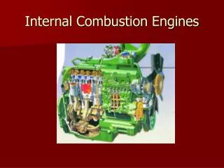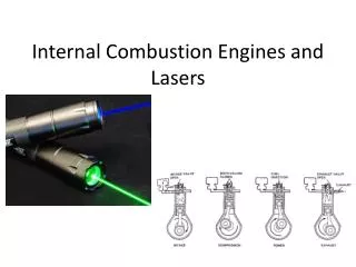
Internal Combustion Engines
Internal Combustion Engines. Faculty - Er. Ashis Saxena. Index. Unit 1 Introduction to I.C Engines Fuels Unit 2 SI Engines Unit 3 CI Engines Unit 4 Engine Cooling Lubrication Supercharging Testing and Performance Unit 5 Compressors. Unit - 2. SI Engines. Chapter – 2.


Internal Combustion Engines
E N D
Presentation Transcript
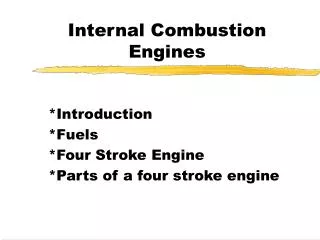
Internal Combustion Engines Faculty - Er. Ashis Saxena
Index Unit 1 • Introduction to I.C Engines • Fuels Unit 2 • SI Engines Unit 3 • CI Engines Unit 4 • Engine Cooling • Lubrication • Supercharging • Testing and Performance Unit 5 • Compressors
Unit - 2 SI Engines Chapter – 2
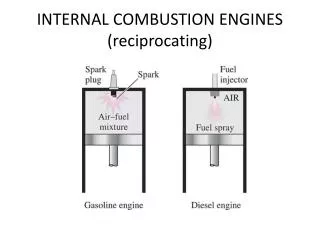
Carburetion In an engine, carburetion is the process of preparation of a proper ratio of oxygen with a gaseous form of a fossil fuel, like natural gas or gasoline, so it can combust. • Internal combustion engines run by igniting fuel that has been sprayed into a fine vapor and mixed with air. This mixture, called an emulsion, will burn with the right amount of energy to fuel the engine. Carburetion usually involves all these stages, from vaporizing the gasoline to letting in the air and finally moving the mixture to where it can be combusted. • Carburetion is responsible for allowing an engine to perform at an optimal level whether it is starting, running at full throttle, or idling. What if carburetion process is absent? • If there is too much fuel or too little oxygen, the engine runs "rich" and wastes fuel, produces smoke, creates too much heat, or ruins parts of the engine. • If there is too little fuel or too much air, the engine runs "lean" and might sputter, stop, or cause engine damage.
Air-fuel Requirement in SI Engines The spark-ignition automobile engines run on a mixture of gasoline and air. The amount of mixture the engine can take in depends upon following major factors: • Engine displacement. • Maximum revolution per minute (rpm) of engine. • Carburetor air flow capacity. • Volumetric efficiency of engine. There is a direct relationship between an engine’s air flow and it’s fuel requirement. This relationship is called the air-fuel ratio.
Air-fuel Ratios • The air-fuel ratio is the proportions by weight of air and gasoline mixed by the carburetor as required for combustion by the engine. • This ratio is extremely important for an engine because there are limits to how rich (with more fuel) or how lean (with less fuel) it can be, and still remain fully combustible for efficient firing. • The mixtures with which the engine can operate range from 8:1 to 18.5:1 i.e. from 8 kg of air/kg of fuel to 18.5 kg of air/kg of fuel. • Richer or leaner air-fuel ratio limit causes the engine to misfire, or simply refuse to run at all.
Air Fuel Mixtures An engine is generally operated at different loads and speeds. For this proper air-fuel mixture should be supplied to the engine cylinder. Fuel and air are mixed to form three different types of mixtures. • Chemically correct mixture: Chemically correct or stoichiometric mixture is one in which there is just enough air for complete combustion of the fuel. Complete combustion means all carbon in the fuel is converted to CO2 and all hydrogen to H2O. For example, to burn one kg of octane (C8H8) completely 15.12 kg of air is required. Hence chemically correct A/F ratio for octane is 15.12:1; usually approximated to 15:1. • Rich mixture: A mixture which contains less air than the stoichiometric requirements is called a rich mixture (example, A/F ratio of 12:1, 10:1 etc.). • Lean mixture: A mixture which contains more air than the stoichiometric requirements is called a lean mixture (example, A/F ratio of 17:1, 20:1 etc.). There is however, a limited range of A/Fratios (approximately 8:1 (rich) to 18.5:1 (lean)), in which combustion in an SI engine will occur. Outside this range, the ratio is either too rich or too lean to sustain flame propagation.
Air Fuel Mixtures (for different throttle operations) For successful operation of the engine, the carburetor has to provide mixtures which follow the general shape of the curve ABCD (single cylinder) A'B'C'D' (multi-cylinder) in Fig. The three general ranges of throttle operation are: • Idling : (mixture must be enriched) • Cruising (mixture must be leaned) • High Power (mixture must be enriched)
Idling • Idling is running a vehicle's engine when the vehicle is not in motion. • This commonly occurs when drivers are stopped at a red light, waiting in a fast food drive-thru lane, or waiting while parked outside a business or residence. • When an engine idles, the engine runs without any loads except the engine accessories.
Should I shut off the engine when I‘m Idling my vehicle • If you're in a drive-through restaurant/business line or waiting for someone and you'll be parked and sitting for 10 seconds or longer... turn off your car's engine. • Why?? • For every two minutes a car is idling, it uses about the same amount of fuel it takes to go about one mile. • But you're not going anywhere. Idling gets ZERO km per liter.
Myths associated with idling Myth #1: The engine should be warmed up before driving. • Reality: Idling is not an effective way to warm up your vehicle, even in cold weather. The best way to do this is to drive the vehicle. With today's modern engines, you need no more than 30 seconds of idling on winter days before driving away. Myth #2: Idling is good for your engine. • Reality: Excessive idling can actually damage your engine components, including cylinders, spark plugs, and exhaust systems. Fuel is only partially combusted when idling because an engine does not operate at its peak temperature. This leads to the build up of fuel residues on cylinder walls that can damage engine components and increase fuel consumption.
Myths associated with idling Myth #3: Shutting off and restarting your vehicle is hard on the engine and uses more gas than if you leave it running. • Reality: Frequent restarting has little impact on engine components like the battery and the starter motor. Component wear caused by restarting the engine is estimated to add $10 per year to the cost of driving, money that will likely be recovered several times over in fuel savings from reduced idling. The bottom line is that more than ten seconds of idling uses more fuel than restarting the engine.
Air Fuel Mixtures (for different throttle operations)Idling range Idling range: • An idling engine is one which operates at no load and with nearly closed throttle. Under idling conditions, the engine requires a rich mixture. This is due to the existing pressure conditions within the combustion chamber and the intake manifold which cause exhaust gas dilution of the fresh charge. • Since, the clearance volume is constant, the mass of exhaust gas in the cylinder at the end exhaust stroke tends to remain constant throughout the idling range. The amount of fresh charge brought, in during idling, however, is much less than that during full throttle operation, due to very small opening of the throttle. This results in a much larger proportion of exhaust gas being mixed with the fresh charge under idling conditions. • Further, with nearly closed throttle the pressure in the intake manifold is considerably below atmospheric due to restriction to the air flow. When the intake valve opens, the pressure differential between the combustion chamber and the intake manifold results in initial backward How of exhaust gases into the intake manifold. As the piston proceeds down on the intake stroke, these exhaust gases are drawn back into the cylinder, along with the fresh charge. As a result, the final mixture of fuel and air in the combustion chamber is diluted more by exhaust gas & the contact of fuel and air particles is obstructed resulting in poor combustion & in loss of power. Hence more fuel is required by richening the air-fuel mixture which improve the probability of contact between fuel and air particles and thus improves combustion. • As the throttle is gradually opened from A to B, the pressure differential between the inlet manifold and the cylinder becomes smaller and the exhaust gas dilution of the fresh charge diminishes.
Air Fuel Mixtures (for different throttle operations)Idling range Cruising Range: • In the cruising range from B to C the exhaust gas dilution problem is relatively insignificant. The primary interest lies in obtaining the maximum fuel economy. Consequently, in this range, it is desirable that the carburetor provides the engine with the best economy mixture. Power Range: During peak power operation the engine requires a richer mixture, as indicated by the line CD for the following reasons: • To provide best power: Since high power is desired, it is logical to transfer the economy settings of the cruising range to that mixture which will produce the maximum power, or a setting in the vicinity of the best power mixture, usually in the range of 12:1. • To prevent overheating of exhaust valve and the area near it: At high power, the increased mass of gas at higher temperatures passing through the cylinder results in the necessity of transferring greater quantities of heat away from critical areas such as those around the exhaust valve. Enriching the mixture reduces the flame temperature and the cylinder temperature. This reduces the cooling problem and also reduces the tendency to damage exhaust valves at high power.
Principle of carburetion • Both air & gasoline are drawn through the carburetor and into the engine cylinders by the suction created by the downward movement of the piston. • It is the difference in pressure between the atmosphere and cylinder that causes the air to flow into the chamber. • In the carburetor, air passing into the combustion chamber picks up fuel discharged from a tube. This tube has a fine orifice called carburetor jet which is exposed to the air path. • In order that the fuel drawn from the nozzle may be thoroughly atomized, the suction effect must be strong and the nozzle outlet comparatively small. • In order to produce a strong suction, the pipe in the carburetor carrying air to the engine is made to have a restriction. At this restriction called throat due to increase in velocity of flow, a suction effect is created. • The restriction is made in the form of a venturi to minimize throttling losses.
Principle of carburetionVenturi tube operation • Venturi tube has a narrower path at the centre so that the flow area through which the air must pass considerably reduced. • As the same amount of air must pass through every point in the tube, its velocity will be greatest at the narrowest point. • The smaller the area, the greater will be the velocity of the air, and thereby suction is proportionately increased.
Carburetor - Construction & Working • A simple carburetor mainly consists of a float chamber, fuel discharge nozzle & a metering orifice, a venturi, a throttle valve and a choke. • The float & needle valve system maintains a constant level of gasoline in the float chamber. If the amount of fuel in the float chamber falls below the designed level, the float goes down, thereby opening the fuel supply valve & admitting fuel. When the designed level has been reached, the float closes the fuel supply valve thus stopping additional fuel flow from the supply system. • During suction stroke air is drawn through the venturi. Venturi tube is also known as the choke tube and is so shaped that it offers minimum resistance to the air flow. As the air passes through the venturi the velocity increases reaching a maximum at the venturi throat. Correspondingly, the pressure decreases reaching a minimum.
Choke Valve Fuel discharge nozzle Venturi Throttle Valve
Carburetor - Construction & Working • From the float chamber, the fuel is fed to a discharge jet, the tip of which is located in the throat of the venturi. Because of the differential pressure between the float, chamber and the throat of the venturi, known as carburetor depression, fuel is discharged into the air stream. • The gasoline engine is quantity governed, which means that when power output is to be varied at a particular speed, the amount of charge delivered to the cylinder is varied. This is achieved by means of a throttle valve usually of the butterfly type which is situated after the venturi tube. • As the throttle is closed less air flows through the venturi tube and less is the quantity of air-fuel mixture delivered to the cylinder and hence power output is reduced. • As the throttle is opened, more air flows through the choke tube resulting in increased quantity of mixture being delivered to the engine. This increases the engine power output.
Combustion in SI engine • The combustion is defined as a rapid chemical reaction between the hydrogen and carbon with oxygen in the air and liberates energy in the form of heat. • The conditions necessary for combustion are the presence of combustible mixture and some means of initiating the process. • The process of combustion in engines generally takes place either in a homogeneous or a heterogeneous fuel vapor-air mixture depending on the type of engine. • In an SI engine Fuel and air are homogeneously mixed together in the intake system, inducted through the intake valve into the cylinder where it mixes with residual gases and is then compressed. • Under normal operating conditions, combustion is initiated towards the end of the compression stroke at the spark plug by an electric discharge. A turbulent flame develops following the ignition and propagates through this premixed charge of fuel and air, and also the residual gas in the clearance volume until it reaches the combustion chamber walls.
Stages of Combustion in SI engine A typical pressure-crank angle diagram, during the compression (a b), combustion (b c) and expansion (c d) in an ideal four stroke spark-ignition engine is shown in Fig. In an ideal engine the entire pressure rise during combustion takes place at constant volume i.e., at TDC. However, in an actual engine it does not happen.
Stages of Combustion in SI engine The pressure variation due to combustion in a practical engine is shown below. In this figure, A is the point of passage of spark (say 20° bTDC), B is the point at which the beginning of pressure rise can be detected (say 8° bTDC) and C the attainment of peak pressure. Thus AB represents the first stage, BC the second stage and CD the third stage.
Stages of Combustion in SI engine 1. Ignition lag stage 2. Flame propagation stage 3. After burning stage
Ignition Lag • Sir Ricardo, known as the father of engine research, describes the combustion process in a SI engine as consisting of three stages: • There is a certain time interval between instant of spark and instant where there is a noticeable rise in pressure due to combustion. • This time lag is called IGNITION LAG. • Ignition lag is the time interval in the process of chemical reaction during which molecules get heated up to self ignition temperature, get ignited and produce a self propagating nucleus of flame.
Ignition Lag • The period of ignition lag is shown by path AB. • Ignition lag is very small and lies between 0.00015 to 0.0002 seconds. • An ignition lag of 0.002 seconds corresponds to 35 degree crank rotation when the engine is running at 3000 RPM. • This is a chemical process depending upon the nature of fuel, temperature and pressure, proportions of exhaust gas and rate of oxidation or burning.
Flame propagation stage: • The second stage (BC) is a physical one and it is concerned with spread of the flame throughout the combustion chamber. • The starting point of the second stage is where the first measurable rise of pressure is seen on the indicator diagram i.e., the point where the line of combustion departs from the compression line (point B). • This can be seen from the deviation from the motoring curve.
Flame propagation stage • During the second stage the flame propagates practically at a constant velocity. • Heat transfer to the cylinder wall is low, because only a small part of the burning mixture comes in contact with the cylinder wall during this period. • The rate of heat-release depends largely on the turbulence intensity and also on the reaction rate which is dependent on the mixture composition. • The rate of pressure rise is proportional to the rate of heat release because during this stage, the combustion chamber volume remains practically constant (since piston is near the top dead center).
After burning • The starting point of the third stage is usually taken as the instant at which the maximum pressure is reached on the indicator diagram (point C). • The flame velocity decreases during this stage. • The rate of combustion becomes low due to lower flame velocity and reduced flame front surface. • Since the expansion stroke starts before this stage of combustion, with the piston moving away from the top dead center, there can be no pressure rise during this stage.
Factors influencing the flame speed • The study of factors which affect the velocity of flame propagation is important since the flame velocity influences the rate of pressure rise in the cylinder and it is related to certain types of abnormal combustion that occur in spark-ignition engines. • Turbulence: • The flame speed is quite low in non-turbulent mixtures and increases with increasing turbulence. This is mainly due to the additional physical intermingling of the burning and unburned particles at the flame front which expedites reaction by increasing the rate of contact. The turbulence in the incoming mixture is generated during the admission of fuel air mixture through comparatively narrow sections of the intake pipe, valve openings etc., in the suction stroke. • The increase of flame speed due to turbulence reduces the combustion duration and hence minimizes the tendency of abnormal combustion. However, excessive turbulence may extinguish the flame resulting in rough and noisy operation of the engine.
Factors influencing the flame speed Fuel-Air Ratio: • The fuel-air ratio has a very significant influence on the flame speed. The highest flame velocities (minimum time for complete combustion) are obtained with somewhat richer mixture which shows the effect of mixture strength on the rate of burning as indicated by the time taken for complete burning in a given engine. When the mixture is made leaner or richer the flame speed decreases. Less thermal energy is released in the case of Iean mixtures resulting in lower flame temperature. Very rich mixtures lead to incomplete combustion which results again in the release of less thermal energy. Temperature and Pressure: • Flame speed increases with an increase in intake temperature and pressure. A higher initial pressure and temperature may help to form a better homogeneous air-vapor mixture which helps in increasing the flame speed. This is possible because of an overall inert in the density of the charge.
Factors influencing the flame speed Compression Ratio: • A higher compression ratio increases the pressure and temperature of the working mixture which reduce the initial phase of combustion and hence less ignition advance is needed. High pressures and temperatures of the compressed mixture also speed up the second phase of combustion. Increased compression ratio reduces the clearance volume and therefore increases the density of the cylinder gases during burning. This increases the peak pressure and temperature and the total combustion duration is reduced. Thus engines having higher compression ratios have higher flame speeds.
Factors influencing the flame speed Engine Output: • The cycle pressure increases when the engine output is increased. With the increased throttle opening the cylinder gets filled to a higher density. This results in increased flame speed. When the output is decreased by throttling, the initial and final compression pressures decrease and the dilution of the working mixture increases. The smooth development of self propagating nucleus of flame becomes unsteady and difficult. The main disadvantages of SI engines are the poor combustion at low loads and the necessity of mixture enrichment which causes wastage of fuel and discharge of unburnt hydrocarbon and the products of incomplete combustion like carbon monoxide etc. in the atmosphere.
Factors influencing the flame speed Engine Speed: • The flame speed increases almost linearly with engine speed since the increase in engine speed increases the turbulence inside the cylinder. The time required for the flame to traverse the combustion space would be halved, if the engine speed is doubled. Double the engine speed and hence half the original time would give the same number of crank degrees for flame propagation. The crank angle required for the flame propagation during the entire phase of combustion, will remain nearly constant at all speeds. Engine Size: • The size of the engine does not have much effect on the rate of flame propagation. In large engines the time required for complete combustion is more because the flame has to travel a longer distance. This requires increased crank angle duration during the combustion. This is one of the reasons why large sized engines are designed to operate at low speeds.
Abnormal Combustion • In normal combustion, the flame initiated by the spark travels across the combustion chamber in a fairly uniform manner. • Under certain operating conditions the combustion deviates from its normal course leading to loss of performance and possible damage to the engine. This type of combustion can be termed as an abnormal combustion or knocking combustion. • The consequences of this abnormal combustion process are the loss of power, recurring pre-ignition and mechanical damage to the engine.
Phenomenon of knock in SI engines • In a spark-ignition engine combustion which is initiated between the spark plug electrodes spreads across the combustible mixture. A definite flame front which separates the fresh mixture from the products of combustion travels from the spark plug to the other end of the combustion chamber. • Heat release due to combustion increases the temperature and consequently the pressure, of the burned part of the mixture above those of the unburned mixture. In order to effect pressure equalization the burned part of the mixture will expand, and compress the unburned mixture adiabatically thereby increasing its pressure and temperature. This process continues as the flame front advances through the mixture and the temperature and pressure of the unburned mixture are increased further. • If the temperature of the unburnt mixture exceeds the self-ignition temperature of the fuel and remains at or above this temperature during the period of preflame reactions (ignition lag), spontaneous ignition or auto ignition occurs at various pin-point locations. This phenomenon is called knocking. The process of auto ignition leads towards engine knock.
Phenomenon of knock in SI engines • This phenomenon of knock may be explained by referring to Fig. (a) which shows the cross-section of the combustion chamber with flame advancing from the spark plug location A without knock whereas Fig. (c) shows the combustion process with knock. • Normal Combustion • In the normal combustion the flame travels across the combustion chamber from A towards D. The advancing flame front compresses the end charge BB'D farthest from the spark plug thus raising its temperature. The temperature is also increased due to heat transfer from the hot advancing flame-front. Also some preflame oxidation may take place in the end charge leading to further increase in temperature. In spite of these factors if the temperature of the end charge had not reached its self-ignition temperature, the charge would not auto ignite and the flame will advance further and consume the charge BB‘D. This is the normal combustion process which is illustrated by means of the pressure-time diagram, Fig. (b).
Phenomenon of knock in SI engines • Abnormal Combustion • However, if the end charge BB'D reaches its auto ignition temperature and remains for some length of time equal to the time of preflame reactions the charge will auto ignite, leading to knocking combustion. In Fig. (c), it is assumed that when flame has reached the position BB', the charge ahead of it has reached critical auto ignition temperature. During the preflame reaction period if the flame front could move from BB' to only CC’ then the charge ahead of CC' would auto ignite.
Phenomenon of knock in SI engines • Because of the auto-ignition, another flame front starts traveling in the opposite direction to the main flame front. When the two flame fronts collide, a severe pressure pulse is generated. The gas in the chamber is subjected to compression and rarefaction along the pressure pulse until pressure equilibrium is restored. This disturbance can force the walls of the combustion chambers to vibrate at the same frequency as the gas. Gas vibration frequency in automobile engines is of the order of 5000 cps. The pressure-time trace of such a situation is shown in (d). • It is to be noted that the onset of knocking is very much dependent on the properties of fuel. It is clear from the above description that if the unburned charge does not reach its auto-ignition temperature there will be no knocking. Further, if the initial phase i.e., ignition lag period, is longer than the time required for the flame front to burn through the unburned charge, there will be no knocking. But, if the critical temperature is reached and maintained, and the ignition lag is shorter than the time it takes for the flame front to burn through the unburned charge then the end charge will detonate. Hence, in order to avoid or inhibit detonation, a high auto-ignition temperature and a long ignition lag are the desirable qualities for SI engine fuels.
Phenomenon of knock in SI engines • In summary, when autoignition occurs, two different types of vibration may be produced. In one case a large amount of mixture may autoignite giving rise to a very rapid increase in pressure throughout the combustion chamber and there will be a direct blow on the engine structure. The human ear can detect the resulting thudding sound and consequent noise from free vibrations of the engine parts. In the other case, large pressure differences may exist in the combustion chamber and the resulting gas vibrations can force the walls of the chamber to vibrate at the same frequency as the gas. An audible sound may be evident. • The impact of knock on the engine components and structure can cause engine failure and in addition the noise from engine vibration is always objectionable. • The pressure differences in the combustion chamber cause the gas to vibrate and scrub the chamber walls causing increased loss of heat to the coolant.
Effect of engine variables on knock (Density Factors) • Density Factors • Any factor which reduces the density of the charge tends to reduce knocking by providing lower energy release. • Compression Ratio: • Compression ratio of an engine is an important factor which determines both the pressure and temperature at the beginning of the combustion process. Increase in compression ratio increases the pressure and temperature of the gases at the end of the compression stroke. This decreases the ignition lag of the end gas and thereby increasing the tendency for knocking. The overall increase in the density of the charge due to higher compression ratio increases the preflame reactions in the end charge thereby increasing the knocking tendency of the engine. The increase in the knocking tendency of the engine with increasing compression ratio is the main reason for limiting the compression ratio to a lower value. • Mass of Inducted Charge: • A reduction in the mass of the inducted charge into the cylinder of an engine by throttling or by reducing the amount of supercharging reduces both temperature and density of the charge at the time of ignition. This decreases the tendency of knocking.
Effect of engine variables on knock (Density Factors) Inlet Temperature of the Mixture: • Increase in the inlet temperature of the mixture makes the compression temperature higher thereby, increasing the tendency of knocking. Further, volumetric efficiency will be lowered. Hence a lower inlet temperature is always preferable to reduce knocking. It is important that the temperature should not be so low as to cause starting and vaporization problems in the engine. Temperature of the Combustion Chamber Walls: • Temperature of the combustion chamber walls play a predominant role in knocking. In order to prevent knocking the hot spots in the combustion chamber should be avoided. Since, the spark plug and exhaust valve are two hottest parts in the combustion chamber, the end gas should not be compressed against them.
Effect of engine variables on knock (Density Factors) Retarding the Spark Timing: • By retarding the spark timing from the optimized timing, i.e., having the spark closer to TDC, the peak pressures are reached farther down on the power stroke and are thus of lower magnitude. This might reduce the knocking. However, this will affect the brake torque and power output of the engine. Power Output of the Engine: • A decrease in the output of the engine decreases the temperature of the cylinder and the combustion chamber walls and also the pressure of the charge thereby lowering mixture and end gas temperatures. This reduces the tendency to knock.
Effect of engine variables on knock (Time Factors) • Time Factors • Increasing the flame speed or increasing the duration of the ignition lag or reducing the time of exposure of the unburned mixture to auto-ignition condition will tend to reduce knocking. • Turbulence: Turbulence depends on the design of the combustion chamber and on engine speed. Increasing turbulence increases the flame speed and reduces the time available for the end charge to attain auto-ignition conditions thereby decreasing the tendency to knock. • Engine Speed: An increase in engine speed increases the turbulence of the mixture considerably resulting in increased flame speed, and reduces the time available for preflame reactions. Hence knocking tendency is reduced at higher speeds. • Flame Travel Distance: The knocking tendency is reduced by shortening the time required for the flame front to traverse the combustion chamber. Engine size (combustion chamber size), and spark plug position are the three important factors governing the flame travel distance.
Effect of engine variables on knock (Time Factors) • Engine Size: The flame requires a longer time to travel across the combustion chamber of a larger engine. Therefore, a larger engine has a greater tendency for knocking than a smaller engine since there is more time for the end gas to auto-ignite. Hence, an SI engine is generally limited to size of about 150 mm bore. • Combustion Chamber Shape: Generally, the more compact the combustion chamber is, the shorter is the flame travel and the combustion time and hence better antiknock characteristics. Therefore, the combustion chambers are made as spherical as possible to minimize the length of the flame travel for a given volume. If the turbulence in the combustion chamber is high, the combustion rate is high and consequently combustion time and knocking tendency are reduced. Hence, the combustion chamber is shaped in such a way as to promote turbulence. • Location of Spark Plug: In order to have a minimum flame travel the spark plug is centrally located in the combustion chamber, resulting in minimum knocking tendency. The flame travel can also be reduced by using two or more spark plugs in case of large engines.
Effect of engine variables on knock (Composition Factors) • Composition Factors • Once the basic design of the engine is finalized, the fuel-air ratio and properties of the fuel, particularly the octane rating, play a crucial role in controlling the knock. • Fuel-Air Ratio: The flame speeds are affected by fuel-air ratio. Also the flame temperature and reaction time are different for different fuel-air ratios. Maximum flame temperature is obtained when Ø ≡ 1.1 to I.2 whereas Ø = 1 gives minimum reaction time for auto-ignition. • Figure below shows the variation of knock limited compression ratio with respect to equivalence ratio for iso-octane. The maximum tendency to knock takes place for the fuel-air ratio which gives minimum reaction time.
Effect of engine variables on knock (Composition Factors) • Octane Value of the Fuel: A higher self-ignition temperature of the fuel and a low preflame reactivity would reduce the tendency of knocking. • In general paraffin series of hydrocarbon have the maximum and aromatic series the minimum tendency to knock & the naphthene series comes in between the two. • Usually, compounds with more compact molecular structure are less prone to knock. In aliphatic hydrocarbons, unsaturated compounds show lesser knocking tendency than saturated hydrocarbons, the exception being ethylene, acetylene and propylene.
Combustion Chamber Design • The design of the combustion chamber for an SI engine has an important influence on the engine performance and its knocking tendencies. • The design involves the shape of the combustion chamber, the location of spark plug and the location of inlet and exhaust valves. • Combustion chambers must be designed carefully, keeping in mind the following general objectives. • Smooth Engine Operation • The aim of engine design is to have a smooth operation and a good economy. These can be achieved by the following: • Moderate rate of pressure rise: The rate of pressure rise can be regulated such that the greatest force is applied to the piston as closely after TDC on the power stroke as possible, with a gradual decrease in the force on the piston during the power stroke. The forces must be applied to the piston smoothly, thus limiting the rate of pressure rise as well as the position of the peak pressure with respect to TDC.