Feed & Front End PDR
460 likes | 704 Views
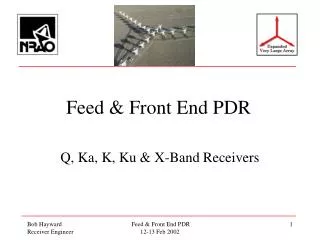
Feed & Front End PDR. Q, Ka, K, Ku & X-Band Receivers. High Frequency Receivers. EVLA Receiver Bands: Q-Band : 40 50 GHz Ka-Band : 26 40 GHz K-Band : 18 26 GHz Ku-Band : 12 18 GHz X-Band : 8 12 GHz. Baseline Design.

Feed & Front End PDR
E N D
Presentation Transcript
Feed & Front End PDR Q, Ka, K, Ku & X-Band Receivers Feed & Front End PDR 12-13 Feb 2002
High Frequency Receivers EVLA Receiver Bands: • Q-Band : 40 50 GHz • Ka-Band : 26 40 GHz • K-Band : 18 26 GHz • Ku-Band : 12 18 GHz • X-Band : 8 12 GHz Feed & Front End PDR 12-13 Feb 2002
Baseline Design • What follows is the preliminary “baseline” design and is an extrapolation of the current VLA receiver concept • To realize the linearity required to carry out Solar observing (with its 70 dB dynamic range requirements) we will need to adopt a new receiver design philosophy & make several major modifications to the current L, Q & K systems • See PAL’s presentation Feed & Front End PDR 12-13 Feb 2002
VLA Receiver History • VLA originally built with L, C, Ku & K bands • All inside a single Dewar (ie: the “A-Rack”) • Required long waveguide runs between Feeds & A-Rack Dewar • For Voyager Encounter in 1986, new X-Band Rx mounted in a separate dewar on the Feed Circle • Followed by VLBA-style L-Band in early 90’s • New Q & K-Band Rx’s installed from mid 90’s • C & Ku-Band still in A-Rack Feed & Front End PDR 12-13 Feb 2002
QAKUX Receivers General Comments • Receivers X-Band all have 8-12 GHz IF’s • Two Circular Polarization IF Pairs • Two independent LO’s and 4 Mixers • Four 8-12 GHz IF’s • RCP-1 & LCP-1 and RCP-2 & LCP-2 • Allows 8 GHz bandwidth per polarization (total BW = 16 GHz) • Common 8-12 GHz IF Down-Converter (4 modules) • K-Band design will be scaled in frequency for Ka, Ku and (probably) X-Band • New feature - Non-Linear Threshold Detectors (NLTD) Feed & Front End PDR 12-13 Feb 2002
QAKUX Receivers Polarizers Feed & Front End PDR 12-13 Feb 2002
TRx EstimatesVLBA vs. EVLA Comparison Note : Does not include noise contribution from Down-Converter Subsystem Feed & Front End PDR 12-13 Feb 2002
Q-Band Receiver Block Diagram • Frequency Coverage = 40 50 GHz • LO Ref Input = 16.6 20.0 GHz @ 0 dBm • Uses Tripler to provide an LO of 50 60 GHz • IF Output = 8-12 GHz @ approx -45 dBm • CDL 4-stage LNA with TN 25K • Estimated TRx 44K Feed & Front End PDR 12-13 Feb 2002
Current VLA Q-Band Receiver (side view) Feed & Front End PDR 12-13 Feb 2002
Current VLA Q-Band Receiver (side view) Feed & Front End PDR 12-13 Feb 2002
Q-Band EVLA Modifications • Retain: • Feed, Polarizer, Isolators, LNA’s (most of them), LO Amp, Passive Triplers, Mixers, Noise Diode, Dewar, Model 22 Fridge • Add: • 2 RF Splitters, 2 Post Amps, Isolators, 2nd Mixer pair, 2nd LO Amp, 2 Triplers (Active?) • Remove: • IF Chain (Filter + Amp) • Uncertain: • Cal Coupler (replace 30 with 20 dB), Card Cage Feed & Front End PDR 12-13 Feb 2002
Q-Band ReceiverMajor Components • Polarizer - Atlantic Microwave Septum • LNA - CDL 4-stage InP HEMT • Post Amp - Spacek Labs (2 x $3.5K) - G = 25dB, NF = 5dB, Po = +4dBm - NRAO HMMC-5040 MMIC ? (20-30 & 40-60 GHz, 10 dB) • Tripler/Mixer - Spacek M45-8.4 (2 x $9.1K) - x2/Mixer Option (2 x $5.6K) Feed & Front End PDR 12-13 Feb 2002
Q-Band Upgrade Incremental Cost (Tripler) Feed & Front End PDR 12-13 Feb 2002
Q-Band Upgrade Incremental Cost (Doubler) Feed & Front End PDR 12-13 Feb 2002
Sensitivity of Current Q-Band Systems Of the 25 populated VLA antennas, we will want to replace 23 out of the 50 existing LNA’s - 20 old GaAs - 3 sub-standard InP Feed & Front End PDR 12-13 Feb 2002
Q-Band Noise Budget Feed & Front End PDR 12-13 Feb 2002
Q-Band Noise Budget(no Post Amp) Feed & Front End PDR 12-13 Feb 2002
K-Band Receiver Block Diagram • Frequency Coverage= 18 26.5 GHz • LO Ref Input = 14.018.25 GHz @ 0 dBm • Uses Doubler to provide an LO of 28 36.5 GHz • IF Output = 8-12 GHz @ approx -45 dBm • CDL 4-stage LNA with TN 15K • Estimated TRx 28K Feed & Front End PDR 12-13 Feb 2002
Current VLA K-Band Receiver (front view) Feed & Front End PDR 12-13 Feb 2002
K-Band EVLA Modifications • Retain: • Feed, Polarizer, Isolators, LNA’s (most of them), Post Amp, • LO Amp, Noise Diode, Dewar, Model 350 Fridge • Add: • 2 RF Splitters, Isolators, 2nd LO Amp, 2 LO Doublers, • 4 new wideband Mixers (last 8 Rx’s have WB Mixers - need 104) • Remove: • Mixers, IF Filters • Uncertain: • Cal Coupler (replace 30 with 20 dB), Card Cage • Post Amps (35 vs 25 dB) Feed & Front End PDR 12-13 Feb 2002
K-Band ReceiverMajor Components • Polarizer - Phase-Shifter + Symmetric OMT • LNA - CDL 4-stage InP HEMT • Post Amp - Quinstar QLN-2240J0 (2 x $1.1K) - G = 25dB, NF = 4dB, Po = +10dBm • Doubler - TBD (2 x $?K) • Mixer - Miteq TB0440LW1 (4 x $1.1K) - RF/LO=4-40 GHz, IF=0.5-20 GHz Feed & Front End PDR 12-13 Feb 2002
K-Band Upgrade Incremental Cost Feed & Front End PDR 12-13 Feb 2002
K-BandOther Considerations • Water Vapor Radiometer • Plans for bolting a WVR system to the bottom of Rx • Temperature stabilize system with Noise Diode, RF splitter, Post Amp plus WVR back end • K-Band design will be scaled up/down in frequency for Ka, Ku & (probably) X-Band • Drawings for K-Band being updated and improved Feed & Front End PDR 12-13 Feb 2002
K-Band SensitivityVLA & VLBA Feed & Front End PDR 12-13 Feb 2002
K-Band Noise Budget Feed & Front End PDR 12-13 Feb 2002
Ka-Band Receiver Block Diagram • Frequency Coverage= 26.5 40 GHz • LO Ref Input = 12.116.6 GHz @ 0 dBm • Uses Tripler to provide an LO of 36.3 49.8 GHz • IF Output = 8 -12 GHz @ approx -45 dBm • CDL 4-stage LNA with TN 20K • Estimated TRx 38K Feed & Front End PDR 12-13 Feb 2002
Ka-Band ReceiverMajor Components • Polarizer - Phase-Shifter + Symmetric OMT • LNA - CDL 4-stage InP HEMT • Post Amp - G = 25 dB, NF = 5dB, Po = +8dBm - Spacek Labs (2 x $2.8K) - NRAO HMMC-5040 MMIC ? (20-30 & 40-60 GHz, 10 dB) • Tripler/Mixer - Spacek (4 x $5.3K) Feed & Front End PDR 12-13 Feb 2002
Ka-Band Noise Budget Feed & Front End PDR 12-13 Feb 2002
Ku-Band Receiver Block Diagram • Frequency Coverage= 12 18 GHz • LO Ref Input = 12.0†14.0 GHz @ 0 dBm • Uses Doubler to provide an LO of 23 28 GHz • IF Output = 8 -12 GHz @ approx -45 dBm • CDL 3-stage LNA with TN 10K • Estimated TRx 21K † poor RF-to-IF isolation at 12 GHz Feed & Front End PDR 12-13 Feb 2002
Ku Down-ConversionThe Wrong Way IF Out Translation of 12-16 GHz LO = 24 GHz Ku-Band Rx Freq (GHz) 7 8 9 10 11 12 13 14 15 16 17 18 19 IF Out Ku-Band Rx Translation of 16-18 GHz LO = 26 GHz Freq (GHz) 7 8 9 10 11 12 13 14 15 16 17 18 19 Feed & Front End PDR 12-13 Feb 2002
Ku Down-ConversionThe Right Way Translation of 12-15 GHz LO = 23 GHz IF Out Ku-Band Rx Freq (GHz) 7 8 9 10 11 12 13 14 15 16 17 18 19 IF Out Ku-Band Rx Translation of 15-18 GHz LO = 26 GHz Freq (GHz) 7 8 9 10 11 12 13 14 15 16 17 18 19 Feed & Front End PDR 12-13 Feb 2002
Ku-Band LO Requirements • Requires that the 1st LO Synthesizer be able to provide 11.5 GHz • Current specification is only 12-20 GHz Feed & Front End PDR 12-13 Feb 2002
Ku-Band ReceiverMajor Components • Polarizer - Phase-Shifter + Symmetric OMT • LNA - CDL 3-stage InP HEMT • Post Amp - G = 25 dB, NF=3dB, Po = +10dBm - TBD (Quinstar 2 x $1K) • Doubler/Mixer - TBD (4 x $?K) • We hope to equip EVLA modified antennas with new Ku-Band Rx’s as they come out of the Barn but the Transition plan also calls for an interim Up-Converter to allow the old “A-Rack” Ku Rx’s to be used if needed (components will eventually be incorporated into new Ku-Band Rx later) Feed & Front End PDR 12-13 Feb 2002
Ku-Band Noise Budget Feed & Front End PDR 12-13 Feb 2002
X-Band Receiver Block Diagram • Frequency Coverage= 8 12 GHz • LO Ref Input = None • “IF” Output = approx -45 dBm • CDL 3-stage LNA with TN 10K (?) • Estimated TRx 21K Feed & Front End PDR 12-13 Feb 2002
X-Band ReceiverMajor Components • Polarizer - Phase-Shifter + Symmetric OMT (or Quad-Ridge OMT + Hybrid) • LNA - CDL 3-stage InP HEMT • Post Amp - G = 25 dB, NF = 2dB, Po = +10dBm - TBD (Quinstar 2 x $1K) Feed & Front End PDR 12-13 Feb 2002
X-BandReceiver Package Feed & Front End PDR 12-13 Feb 2002
X-Band Polarizer Options • Phase Shifter + Symmetric Junction OMT: • Proven design at K-Band • Least-risk option for guaranteed RF performance • But very large Rx package (40 inches) • Quad-Ridge OMT + Hybrid: • Nice & small • Will fit inside current Rx footprint • But difficult to fabricate & RF performance unknown Feed & Front End PDR 12-13 Feb 2002
What About the Old X-Band Receiver? • X-Band : VLBA & VLA Rx’s are identical • Nope: • Septum Polarizer only spec’d for 8.0-8.8 GHz • LNA’s, Post Amps, Model 22 (?) • DT500 Temp Sensors (now use DT471) • Maybe: • Noise Diode (MC 7084) ??? • Cal Splitter, Couplers & Isolators ??? • Hasting Vacuum Sensors (Hastings DV-6R) Feed & Front End PDR 12-13 Feb 2002
X-Band Noise Budget Feed & Front End PDR 12-13 Feb 2002
Estimated ReceiverIF Output Power Feed & Front End PDR 12-13 Feb 2002