Download
1 / 115
1.18k likes | 1.45k Views
Presentation links page for lesson six. 6 System variables. Introduction. Access to special machine functions. Alarm generation. Stop with message. Timers. Suppression of single block , feed hold , & feed override. Access to offsets. Machining center , Turning center.

E N D
Presentation links page for lesson six 6 System variables Introduction Access to special machine functions Alarm generation Stop with message Timers Suppression of single block, feed hold, & feed override Access to offsets Machining center, Turning center Access to current position Access to modal information
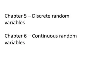
Introduction to system variables Most CNC-related features of parametric programming are accessed with system variables System variable numbering is preset – and varies slightly from one control model to another System variables range from #1000 through about #6000
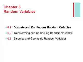
Alarm number (100-255) System variable Alarm message (up to 26 char.) Alarm Generation We introduced alarm generation in lesson four #3000 = 100 (DATA MISSING) Printed on display screen: MC100 DATA MISSING
Alarm Generation Example One example we gave was related to tool width If the tool is too wide, an alarm is sounded G65 P1000 W0.25 T0.125 D0.25 . . . . . IF [#20 LE #23] GOTO 5 #3000 = 100 (TOOL TOO WIDE) N5. . . . . .
A Part Counter Example Another application… O0008 (Main program) . . . N445 G65 P1008 C250. N450 M30 #500: Part counter (Starts at zero) Invoke part counter (C is number of parts to make) Alarm will sound after part count is achieved O1008 #500 = #500 +1 IF[#500 LT #3] GOTO 99 #500 = 0 #3000 = 100 (PART COUNT ACHIEVED) N99 M99
Stop With Message You know the function of M00 program stop M00: Program Stop N140 M00 (TURN PART AROUND)
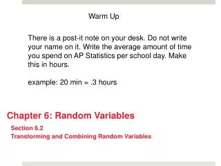
Message number (100-255) System variable Message (up to 26 char.) Stop With Message Stop with message is like M00, but a message will be displayed! #3006 = 100 (REVERSE PART) MS100 REVERSE PART Same structure as alarm generation #3000 Operator can continue by pressing cycle start
Timers You can time events with custom macro! #3001: milliseconds timer #3002: hour timer #3011: Year/month/day #3012: Hour/minute/second
Timers Accumulate the time a tool cuts: . . #3001 = 0 G01 Z-0.5 F4.0 #501 = #501 + #3001 IF [#501 GT 20000] GOTO 98 . . GOTO 99 N98 #501 = 0 (Reset accumulator) #3000 = 100 (TOOL EXHAUSTED) N99 M30 #3001 = 0 (Reset ms timer) #501: Accumulator After twenty seconds of cutting, alarm will sound
Suppression Of Single Block You can actually disable single block! #3003 = 1 (Suppress single block) #3003 = 0 (Enable single block)
Suppression Of Feed Hold You can also disable feed hold! #3004 = 1 (Suppress feed hold) #3004 = 0 (Enable feed hold)
Suppression Of Feedrate Override As well as feedrate override! #3004 = 2 (Suppress feedrate override) #3004 = 0 (Enable feedrate override) #3004 = 3 (Suppress FH & FO) Suppresses both feed hold and feedrate override #3004 = 0 (enables both feedrate override and feed hold)
#18 #26 G65 P1000 R.2 Z-1.0 F0.0625 #9 Tapping Example Call to tapping custom macro O1000 (Tapping program) G00 X0 Z#18 #3003 = 1 (Disable single block) #3004 = 2 (Disable feed hold & feed override) G01 Z#26 F#9 M04 Z#18 #3003 = 0 (Enable single block) #3004 = 0 (Enable feed hold & feed override) M99 Suppresses single block, feed hold, and feedrate override during tapping
OFFSETS 001 00.0000 002 00.0000 003 00.0000 004 00.0000 005 00.0000 006 00.0000 007 00.0000 008 00.0000 009 00.0000 010 00.0000 011 00.0000 012 00.0000 013 00.0000 014 00.0000 015 00.0000 016 00.0000 Machining Center Tool Offsets Machining centers offset tables vary… One value per offset: #2001 - #2199: Offsets 1 - 199
OFFSETS H D H D 001 00.0000 00.0000 002 00.0000 00.0000 003 00.0000 00.0000 004 00.0000 00.0000 005 00.0000 00.0000 006 00.0000 00.0000 007 00.0000 00.0000 008 00.0000 00.0000 009 00.0000 00.0000 010 00.0000 00.0000 011 00.0000 00.0000 012 00.0000 00.0000 013 00.0000 00.0000 014 00.0000 00.0000 015 00.0000 00.0000 016 00.0000 00.0000 Machining Center Tool Offsets Two values per offset: #2001 - #2199: H offsets 1 - 199 #2401 - #2599: D offsets 1 - 199
GEOMETRY OFFSETS H D H D 001 00.0000 00.0000 002 00.0000 00.0000 003 00.0000 00.0000 004 00.0000 00.0000 005 00.0000 00.0000 006 00.0000 00.0000 007 00.0000 00.0000 008 00.0000 00.0000 009 00.0000 00.0000 010 00.0000 00.0000 011 00.0000 00.0000 012 00.0000 00.0000 013 00.0000 00.0000 014 00.0000 00.0000 015 00.0000 00.0000 016 00.0000 00.0000 Machining Center Tool Offsets If you have geometry & wear offsets: #2001 - #2199: H geom offsets 1 - 199 #2401 - #2599: D geom offsets 1 - 199
WEAR OFFSETS H D H D 001 00.0000 00.0000 002 00.0000 00.0000 003 00.0000 00.0000 004 00.0000 00.0000 005 00.0000 00.0000 006 00.0000 00.0000 007 00.0000 00.0000 008 00.0000 00.0000 009 00.0000 00.0000 010 00.0000 00.0000 011 00.0000 00.0000 012 00.0000 00.0000 013 00.0000 00.0000 014 00.0000 00.0000 015 00.0000 00.0000 016 00.0000 00.0000 Machining Center Tool Offsets If you have geometry & wear offsets: #2201 - #2399: H wear offsets 1 - 199 #2601 - #2799: D wear offsets 1 - 199
Machining Center Tool Offsets If you have over 200 offsets: #10001 - #10999: H geom offsets 1-999 #12001 - #12999: D geom offsets 1-199 #11001 - #11999: H wear offsets 1-999 #13001 - #13999: D wear offsets 1-999 All offsets are accessible through custom macro! (Read and Write) You must reference your control manual!
OFFSETS 001 00.0000 002 00.0000 003 00.0000 004 00.0000 005 00.0000 006 00.0000 007 00.0000 008 00.0000 009 00.0000 010 00.0000 011 00.0000 012 00.0000 013 00.0000 014 00.0000 015 00.0000 016 00.0000 Machining Center Tool Offsets Most common: The most common offset configuration is but one value per offset! We’ll assume this for our examples #2001 - #2199: Offsets 1 - 199
Machining Center Tool Offsets #2001 = 3.4563 Sets offset one to 3.4563 #2001 = #2001 + 0.004 Increases offset one by 0.004 Remember, G10 allows offset entry
Machining Center Tool Offsets #101 = #2001 Sets variable #101 to the current value of offset one Not possible by any other means!
Machining Center Tool Offsets Implications: We’ll show several applications a little later! • Testing offsets • Modifying compensation functions • Inventing new compensation functions!
15M FANUC WORK ZERO OFFSET O0040 N00000 NO. 00 (COMMON)X 00.0000Y 00.0000Z 00.0000 NO. 02 (G55)X 00.0000Y 00.0000Z 00.0000 NO. 01 (G54)X 00.0000Y 00.0000Z 00.0000 NO. 03 (G56)X 00.0000Y 00.0000Z 00.0000 EDIT *** STOP **** *** *** *** *** **** + POSITION PROGRAM OFFSET PRG_CHK Machining Center Fixture Offsets You also have access to fixture offsets
Offset #1 (G54) Offset #2 (G55) Offset #3 (G56) Common (#0) X: #5201 Y: #5202 Z: #5203 4th: #5204 X: #5221 Y: #5222 Z: #5223 4th: #5224 X: #5241 Y: #5242 Z: #5243 4th: #5244 X: #5261 Y: #5262 Z: #5263 4th: #5264 Machining Center Fixture Offsets Related system variables:
Offset #4 (G57) Offset #5 (G58) Offset #6 (G59) X: #5281 Y: #5282 Z: #5283 4th: #5284 X: #5301 Y: #5302 Z: #5303 4th: #5304 X: #5321 Y: #5322 Z: #5323 4th: #5324 Machining Center Fixture Offsets Related system variables:
Machining Center Fixture Offsets Do you have the additional fixture offset option? 48 fixture offsets? (G54.1) They’re accessed by the #7000 series system variables
O0001 N005 G54 G90 S300 M03 N010 G00 X0 Y0 N015 G43 H01 Z0.1 N020 G65 P1000 X0 Y0 Z0 H2. T1. D1.0 F4. N025 G91 G28 Z0 M19 N030 M01 . . D H Y X F - Feedrate Z T Simulating Cutter Radius Comp. We’ve specified the cutter size in the calling command First example: D specifies tool diameter
D O1000 G00 X[#24-#7/2] Y[#25-#7/2 -.1] Z[#26 - #20 -.05] G01 Y[#25 + #11 + #7/2] F#9 G00 Z[#26 + 0.1] M99 Simulating Cutter Radius Comp. We’ve referenced cutter size in the custom macro… #11 H Y #25 X #24 #7 #9 F - Feedrate Z T #26 #20
O0001 N005 G54 G90 S300 M03 N010 G00 X0 Y0 N015 G43 H01 Z0.1 N020 G65 P1000 X0 Y0 Z0 H2. T1. D31. F4. N025 G91 G28 Z0 M19 N030 M01 . . Simulating Cutter Radius Comp. But maybe you want the call statement to include the cutter compensation offset number H Y X Now D specifies cutter comp offset number! F - Feedrate Z T D: Offset #
D O1000 #101= #[2000 + #7] G00X[#24-#101] Y[#25-#101 -.1] Z[#26 - #20 -.05] G01 Y[#25 + #11 + #101] F#9 G00 Z[#26 + 0.1] M99 Simulating Cutter Radius Comp. Store value of offset in #101 #11 H Y #25 X #24 #7 Reference offset value #9 F - Feedrate Z T #26 #20
3.000 Simulating Wear Offsets You know how to use wear offsets on turning centers Measured: 3.004 Adjust wear offset by -0.004
FANUC Simulating Wear Offsets 15T In custom macro B: WEAR OFFSETS O0040 N00000 X Z R T 001 -00.0040 00.0000 00.0000 0 002 00.0000 00.0000 00.0000 0 003 00.0000 00.0000 00.0000 0 004 00.0000 00.0000 00.0000 0 005 00.0000 00.0000 00.0000 0 006 00.0000 00.0000 00.0000 0 007 00.0000 00.0000 00.0000 0 EDIT *** STOP **** *** *** *** *** **** + POSITION PROGRAM OFFSET PRG_CHK
0.500 Simulating Wear Offsets Many machining centers don’t have wear offsets! Actual: 0.498 Adjust by -0.002
FANUC Simulating Wear Offsets The tool length compensation offset must be adjusted 15M TOOL OFFSETS O0040 N00000 001 05.5836 002 04.5456 003 08.4736 004 05.3421 005 08.4733 006 06.5947 007 07.4432 008 06.5543 009 00.0000 010 00.0000 011 00.0000 012 00.0000 013 00.0000 014 00.0000 015 00.0000 016 00.0000 EDIT *** STOP **** *** *** *** *** **** + POSITION PROGRAM OFFSET PRG_CHK
FANUC Simulating Wear Offsets Pick a secondary offset to use as the wear offset 15M TOOL OFFSETS O0040 N00000 084 00.0000 095 00.0000 086 00.0000 087 00.0000 088 00.0000 089 00.0000 090 00.0000 091 00.0000 092 00.0000 093 00.0000 094 00.0000 095 00.0000 096 00.0000 097 00.0000 098 00.0000 099 00.0000 EDIT *** STOP **** *** *** *** *** **** + POSITION PROGRAM OFFSET PRG_CHK
FANUC Simulating Wear Offsets Store the deviation in this offset 15M TOOL OFFSETS O0040 N00000 084 00.0000 095 00.0000 086 00.0000 087 00.0000 088 00.0000 089 00.0000 090 00.0000 091 00.0000 092 00.0000 093 00.0000 094 00.0000 095 00.0000 096 00.0000 097 00.0000 098 00.0000 099 -00.0020 EDIT *** STOP **** *** *** *** *** **** + POSITION PROGRAM OFFSET PRG_CHK
Simulating Wear Offsets In the program… O0001 N005 T01 M06 N010 G54 G90 S600 M03 T02 N015 G00 X3.0 Y2.0 N020 G43 Z0.1 N025 G01 Z-[0.5 - #2099] F4.0 N030 X4.5 N035 . . . . .
Simulating Wear Offsets In the program… O0001 N005 T01 M06 N010 G54 G90 S600 M03 T02 N015 G00 X3.0 Y2.0 N020 G43 Z0.1 N025 G01 Z-[0.5 - #2099] F4.0 N030 X4.5 N035 . . . . .
Simulating Wear Offsets In the program… O0001 N005 T01 M06 N010 G54 G90 S600 M03 T02 N015 G00 X3.0 Y2.0 N020 G43 Z0.1 N025 G01 Z-[0.5 - #2099] F4.0 N030 X4.5 N035 . . . . .
Simulating Wear Offsets In the program… O0001 N005 T01 M06 N010 G54 G90 S600 M03 T02 N015 G00 X3.0 Y2.0 N020 G43 Z0.1 N025 G01 Z-[0.5 - #2099] F4.0 N030 X4.5 N035 . . . . .
Simulating Wear Offsets In the program… O0001 N005 T01 M06 N010 G54 G90 S600 M03 T02 N015 G00 X3.0 Y2.0 N020 G43 Z0.1 N025 G01 Z-[0.5 - #2099] F4.0 N030 X4.5 N035 . . . . .
Simulating Wear Offsets In the program… O0001 N005 T01 M06 N010 G54 G90 S600 M03 T02 N015 G00 X3.0 Y2.0 N020 G43 Z0.1 N025 G01 Z-[0.5 - #2099] F4.0 N030 X4.5 N035 . . . . .
Simulating Wear Offsets In the program… O0001 N005 T01 M06 N010 G54 G90 S600 M03 T02 N015 G00 X3.0 Y2.0 N020 G43 Z0.1 N025 G01 Z-[0.5 - #2099] F4.0 N030 X4.5 N035 . . . . . Subtract the value of offset 99 from the programmed Z position
Checking Offsets For Correctness Have you ever wished you could test the operator’s entry of tool offsets to confirm that they are in an acceptable range?
#8 #11 #2 #19 Checking Offsets For Correctness Here’s how you can! O0001 (Main program) / N005 G65 P1000 B1. E12. S3. H11. N010 T01 M06 N015 G54 G90 S500 M03 . . . B: Beginning offset to test E: Ending offset to test S: Shortest acceptable length H: Longest acceptable length
Checking Offsets For Correctness Here’s the testing custom macro: O1000 (Offset tester) #101 = #2 (Counter, also offset number) N1 IF[#101 GT #8] GOTO 99 (Test if finished) IF[#[2000 + #101] GE #19] GOTO 5 (Ok so far) #3000 = 100 (TOOL TOO SHORT) N5 IF[#[2000 + #101] LE #11] GOTO 6 (Tool ok) #3000 = 101 (TOOL TOO LONG) N6 #101 = #101 +1 (Step counter/offset number) GOTO 1 (Go back to the loop test) N99 M99
Checking Offsets For Correctness Program number O1000 (Offset tester) #101 = #2 (Counter, also offset number) N1 IF[#101 GT #8] GOTO 99 (Test if finished) IF[#[2000 + #101] GE #19] GOTO 5 (Ok so far) #3000 = 100 (TOOL TOO SHORT) N5 IF[#[2000 + #101] LE #11] GOTO 6 (Tool ok) #3000 = 101 (TOOL TOO LONG) N6 #101 = #101 +1 (Step counter/offset number) GOTO 1 (Go back to the loop test) N99 M99
Checking Offsets For Correctness Initialize the counter to the first offset to tes O1000 (Offset tester) #101 = #2 (Counter, also offset number) N1 IF[#101 GT #8] GOTO 99 (Test if finished) IF[#[2000 + #101] GE #19] GOTO 5 (Ok so far) #3000 = 100 (TOOL TOO SHORT) N5 IF[#[2000 + #101] LE #11] GOTO 6 (Tool ok) #3000 = 101 (TOOL TOO LONG) N6 #101 = #101 +1 (Step counter/offset number) GOTO 1 (Go back to the loop test) N99 M99
Checking Offsets For Correctness Test if current offset number is greater than last offset number to test O1000 (Offset tester) #101 = #2 (Counter, also offset number) N1 IF[#101 GT #8] GOTO 99 (Test if finished) IF[#[2000 + #101] GE #19] GOTO 5 (Ok so far) #3000 = 100 (TOOL TOO SHORT) N5 IF[#[2000 + #101] LE #11] GOTO 6 (Tool ok) #3000 = 101 (TOOL TOO LONG) N6 #101 = #101 +1 (Step counter/offset number) GOTO 1 (Go back to the loop test) N99 M99
Checking Offsets For Correctness If offset value is larger than shortest acceptable value, offset is okay so far – GOTO next test O1000 (Offset tester) #101 = #2 (Counter, also offset number) N1 IF[#101 GT #8] GOTO 99 (Test if finished) IF[#[2000 + #101] GE #19] GOTO 5 (Ok so far) #3000 = 100 (TOOL TOO SHORT) N5 IF[#[2000 + #101] LE #11] GOTO 6 (Tool ok) #3000 = 101 (TOOL TOO LONG) N6 #101 = #101 +1 (Step counter/offset number) GOTO 1 (Go back to the loop test) N99 M99