Download
1 / 3
30 likes | 110 Views
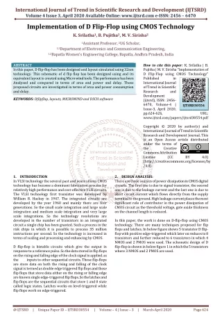
In this paper, D flip flop has been designed and layout simulated using 32nm technology. This schematic of d flip flop has been designed using and its equivalent layout is created using Micro wind tools. The performance has been Analysed and compared in terms of area and power and delay. These proposed circuits are investigated in terms of area and power consumption and delay. K. Srilatha | B. Pujitha | M. V. Sirisha "Implementation of D Flip-Flop using CMOS Technology" Published in International Journal of Trend in Scientific Research and Development (ijtsrd), ISSN: 2456-6470, Volume-4 | Issue-3 , April 2020, URL: https://www.ijtsrd.com/papers/ijtsrd30554.pdf Paper Url :https://www.ijtsrd.com/engineering/electronics-and-communication-engineering/30554/implementation-of-d-flipflop-using-cmos-technology/k-srilatha<br>

E N D
International Journal of Trend in Scientific Research and Development (IJTSRD) Volume 4 Issue 3, April 2020 Available Online: www.ijtsrd.com e-ISSN: 2456 – 6470 Implementation of D Flip-Flop using CMOS Technology K. Srilatha1, B. Pujitha2, M. V. Sirisha2 1Assistant Professor, 2UG Scholar, 1,2Department of Electronics and Communication Engineering, 1,2Bapatla Women’s Engineering College, Bapatla, Andhra Pradesh, India ABSTRACT In this paper, D flip-flop has been designed and layout simulated using 32nm technology. This schematic of d flip flop has been designed using and its equivalent layout is created using Micro wind tools. The performance has been Analysed and compared in terms of area and power and delay. These proposed circuits are investigated in terms of area and power consumption and delay. KEYWORDS: Dfilpflop, layouts, MICROWIND and DSCH software How to cite this paper: K. Srilatha | B. Pujitha | M. V. Sirisha "Implementation of D Flip-Flop using CMOS Technology" Published in International Journal of Trend in Scientific Research and Development (ijtsrd), ISSN: 2456- 6470, Volume-4 | Issue-3, April 2020, pp.624-626, www.ijtsrd.com/papers/ijtsrd30554.pdf Copyright © 2020 by author(s) and International Journal of Trend in Scientific Research and Development Journal. This is an Open Access article distributed under the terms of the Creative Commons Attribution License (CC (http://creativecommons.org/licenses/by /4.0) 2.DESIGN ANALYSIS: There are three sources of power dissipation in CMOS digital circuits. The first one is due to signal transistor, the second one is due to the leakage current and the last one is due to short circuit current which flows directly from the supply terminal to the ground. High leakage current places the most significant role of contributor in the power dissipation of CMOS circuit as the threshold voltage, gate oxide thickness on the channel length is reduced. In this paper, the work is done on D-flip-flop using CMOS technology. There are many techniques proposed for flip flops and latches. In below figure shows 5 transistor D flip- flop with positive edge-triggered which later on reduces to 8 transistors and further reduced to 6 transistors in which 4 NMOS and 2 PMOS were used. The schematic design of D flip-flop is shown in below figure 1 in which the 5 transistors where 3 NMOS and 2 PMOS are used. IJTSRD30554 URL: BY 4.0) 1.INTRODUCTION In VLSI technology the several past and years silicon CMOS technology has become a dominant fabrication process for relatively high performance and cost-effective VLSI circuits. The VLSI technology first transistor was developed by William B. Hackey in 1947. The integrated circuits are developed by the year 1960 and mainly there are four generations. So the small scale integration and large scale integration and medium scale integration and very large scale integrations. So the technology resolutions are developed in the number of transistors in an integrated circuit a single chip has been granted. Such a process in the risk chips in which it is possible to process 35 million instructions per second. So the technology is increased in terms of scaling and processing and enhancing by CMOS. D flip-flop is bistable circuits which give the output in response to a reference pulse. So the data stored in flip flops on the rising and falling edge of the clock signal is applied. as the inputs to other sequential circuits. Those flip-flops are store data on both the rising and falling of the clock signal is termed as double edge triggered flip flops and those flip flops that store data either on the rising or falling edge are known single edge-triggered flip flops. So the latches and flip flops are the sequential circuits that store 1 and 0 state called logic states. Latches works on level-triggered while flip flops work on edge-triggered. @ IJTSRD | Unique Paper ID – IJTSRD30554 | Volume – 4 | Issue – 3 | March-April 2020 Page 624
International Journal of Trend in Scientific Research and Development (IJTSRD) @ www.ijtsrd.com eISSN: 2456-6470 Fig: Timing Diagram of D Flip flop The DSCH timing diagram represents the CMOS Full swing circuit. So the Timing Diagram gives the power and delay of verified in the truth table. 4.LAYOUT DESIGN ANALYSIS: The layout simulations occur in Micro Wind software. So the simulation results performed in the d flip flop layout is consist of p diffusion and n diffusion and metal and contact cuts and substrate. So the layout is consists of delay and power and time and power consumption and area. So this layout is designed in 32nm technology in 6metals and 1NMOS and 3 PMOS is used. This layout is consists of IME is 5ns and the delay is 9sec. so the width is 3.38um and height is 16.5um. So the layout diagram is shown in the below figure. Fig: D Flip flop Block Diagram D flip-flop terms into a multi-threshold CMOS technology when 1 PMOS transistor and 1 NMOS transistor are connected to the circuit of D flip-flop so the clock is high and input is low due to transistor M1 and M2 are on and M3 and M4 are off and the M5 transistor is on due to the output is low. The clock is high the input is high this transistor M1 is off and M2, M3, M4 transistors are on and the M5 transistor is off due to the output is high state i.e. High impudence state. In another way the clock is low state due to the input is the low state and the M1 transistor is on and M2, M2, M3, M4, M5 transistors are off due to the output is low state. 3.SCHEMATIC DESIGN SIMULATION: After designing the initial schematic in the below figure, we test the running of the circuit in DSCH for further analysis. So the circuit is designed in DSCH software simulations occurred. The data stored is one then the outputs will the same. Fig: Layout Diagram of D Flip flop So the D flip-flop is designed in analog simulations and Mos characteristics and 3D and 2D views. So the diagram is shown below. Fig: Simulation of D Flip flop Further, then we study the timing diagram of the circuit in DSCH and compare it with an ideal circuit timing diagram. This generated timing diagram is shown in the below figure. Fig: Analog Simulation of D Flip flop @ IJTSRD | Unique Paper ID – IJTSRD30554 | Volume – 4 | Issue – 3 | March-April 2020 Page 625
International Journal of Trend in Scientific Research and Development (IJTSRD) @ www.ijtsrd.com eISSN: 2456-6470 The analog simulation of d flip-flop is designed due to the current and voltages and currents to voltage and voltage to current and voltage to voltage. So it is simulated in 32nm technology. Specifications Area Delay Power consumption Table: Performance Results of D Flip flop D flip-flop 56.4um2 9sec 0.20uW For a D Flip flop using 32nm technology in Micro wind, the simulation results are mentioned in the above table. The D flip flop is occupied 56.4um2 of the area and has a delay 9 sec. The power consumption due to the width to length is 0.20uW. 6.CONCLUSION: We have successfully designed and simulated our CMOS based D flip flop using Micro wind and DSCH tools. In our design, we have obtained layout, area, power consumption, and delay. So we observed that power consumption decreases and the area increases. The simulation results are based on micro-wind and it gives good driving ability with good output signal and better performance. 7.REFERENCES: [1]Kaphungkui NK. Design of low-power, high- performance flip-flops. International Journal of Applied Sciences and Engineering Research. 2014; 3(4):899- 906. [2]Ziabakhsh S, Zoghi M. Design of a low-power highspeed t-flip-flop using the gate-diffusion input technique. In telecommunications forum TELFOR 2009 (pp. 1470-3). [3]Leblebici Y. CMOS digital integrated circuits: analysis and design. McGraw-Hill [4]Saxena A, Shinghal D, Shinghal K, Mukherjee S. Design and implementation of adiabatic based low power logic circuits. International Research Journal of Engineering and Technology. 2015; 2(2):498-504. Malhotra and Mehra 226 [5]Raj P, Mehra R. Performance and analysis of T flip flop using 90nm CMOS technology. International Journal of Electrical and Electronics Engineers. 2015; 7(1): 192-8. [6]Anjana S, Mehra R. Design and implementation of SR flip flop for efficient power using 90nm CMOS technology. International Journal of Scientific Research Engineering and Technology. 2015; 4(5):480-3. [7]Pinki, Mehra R. Design of low power high-performance JK flip-flop. EATHD conference proceeding 2015 (pp.1- 4). [8]Rahi PK, Dewangan S, Yadav T, Haque Md M. Design simulation and preferences analysis of JK flip flop using various CMOS techniques. International Journal for Research in Emerging Science and Technology.2015; 2(5):169-72. [9]Weste NH, Harris D. CMOS VLSI design: a circuits and systems perspective. Pearson Education India; 2015. [10]Mano M. M, Kime, C. Logic and computer design fundamentals. Pearson; 2013. [11]Aggarwal D. Review of the flip-flop. Journal of Basic Applied and Engineering Research. 2014; 1(10):4-19. [12]Wolf W. Modern VLSI design. Second Edition. Prentice- Hall; 1994. [13]Gupta P, Mehra R. Low power design of SR flip-flop using 45nm technology. IOSR Journal of VLSI and Signal Processing. 2016; 6(2):54-7. [14]Kaur U, Mehra R. Low power CMOS counter using clock gated flip-flop. International Journal of Engineering and Advanced Technology. 2013; 2(4):796-8. Fig: Voltage to Voltage Analog Simulation Waveform. The above figure shows the voltage to voltage characteristics is in the range of 0.6 to 1.2 volts. So the diagram to represent the voltage is increased due to the power is also increased. So the consists of 3pmos and 2nmos transistors used. The 3D view of the D Flip flop is due to all process is completed in the layout. Fig: 3D View of D Flip flop The Mos characteristics of the layout are due to the current and voltages. So the drain to source current and drain to source voltage VDS is to be considered. So the characteristics are due to the current is 5ns and the delay is 9sec. The Mos size of the characteristics due to width is 0.2um and width is 0.1us. Fig: Mos Characteristics of D Flip flop 5.RESULT: The performance analysis of D Flip flop to find out the Delay, Power Consumption and Area using 32nm technology @ IJTSRD | Unique Paper ID – IJTSRD30554 | Volume – 4 | Issue – 3 | March-April 2020 Page 626