Download
1 / 24
240 likes | 404 Views
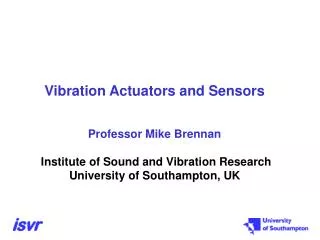
FPU STM: Warm and cold vibration. PACS IHDR. Reinhard Katterloher. Purpose and history of PACS FPU-STM warm and cold vibration.

E N D
FPU STM: Warm and cold vibration PACS IHDR Reinhard Katterloher PACS FPU STM vibration
Purpose and history of PACS FPU-STM warm and cold vibration • Purpose: Design verification of FPU structureRFW-0002 issued and approved, RFW-0002 requests the application of notches in order not to exceed the design limit loads in the FPU feet • Warm vibration of FPU-STM with qualification load levels was successfully finished in January 2003 at MPE, • About 90 accelerometers were installed in the FPU to get information about I/F loads on subunits and to validate the PACS FPU structural modelling • No failure or break occurred • Verification of FPU structure design achieved • Need for minor mechanical improvement on the 3-axis suspension strut identified to shift f0Z to >100 Hz (design upgrade performed after the test) PACS FPU STM vibration
FPU STM mounted on MPE shaker (X & Y/Z-axis configuration) PACS FPU STM vibration
Purpose of PACS FPU-STM cryogenic vibration • Based on this success, MPE proposed to replace the FPU-CQM cryo-vibration by an additional FPU-STM vibration at LHe temperature,RFW-0007 (STM cryo-vibration) issued on 13-05-2003, approval pending until delta-qualification program of subunits is agreed with ESA • Cryogenic vibration qualification of FPU-STM was performed at CSL from 26 May to 2 July 2003 • For time saving reasons in the already de-scoped CQM ILT calibration program (no use of TUFIR facility at LENS for wavelength calibration), no cryogenic qualification of the FPU-CQM is planned by MPE any more before delivery of CQM FPU and AVM WE to ESA PACS FPU STM vibration
Preparation of FPU-STM for cryogenic vibration with qualification load levels at CSL • FPU-STM structure is identically manufactured to FPU-CQM structure • “Upgraded” FPU-STM was equipped with QM components (e.g., QM- detector modules) and with EM or STM models of main FPU subunits (e.g., grating assembly, PhFPU, filter wheel, calibration source etc.) • CQM components replaced by mass dummies (e.g., chopper) and EM or STM components or subunits need a separate additional cryogenic qualification at subunit-level • Last minute actions and remaining problems :- Time for preparation of the test campaign was very short- Cooling straps designed and manufactured by MPE - Limited space inside the CSL vibration cryostat: CoG is off axis- Mechanical properties of VTA not satisfying PACS FPU STM vibration
Configuration matrix of FPU-STM as built for cryo-vibration PACS FPU STM vibration
Integration of PACS subunits with the FPU-STM QM Ge:Ga arrays, EM calibration source, EM filter wheel, EM grating assembly PACS FPU STM vibration
PACS adapter plate mounted on CSL cryo-vibration facility PACS FPU STM vibration
Integrated PACS FPU-STM on CSL cryo-facility (1) PACS FPU STM vibration
Integrated PACS FPU-STM on CSL cryo-facility (2) PACS FPU STM vibration
The facts: cryogenic vibration PACS FPU-STM • PACS test runs were the first instrument cryogenic qualification runs with the new CSL shaker facility • All test activities were performed in close team work with CSL staff, supervised by ESA • Integration activities performed as planned • Cool-down in 3.1 days, predicted from TMM: 3.4 days • PACS temperature during test runs 15K • Notching applied for 1st eigenmode in all axes according RFW-0002 PACS FPU STM vibration
Results: cryogenic vibration PACS FPU-STM • Z- and Y-axis runs successfully performed on 6/7/8 June- data evaluation complicated because of the low fundamental mode of the adapter plate (145Hz)- eigenmode of PACS FPU in Z-axis is 104 Hz- eigenmode of PACS FPU in Y-axis is 122 Hz • Reconfiguration of cryo-facility for vertical axis started on 16 June • X-axis run performed on 23rd June 2003- eigenmode of PACS FPU in X-axis is 188 Hz • No problems observed except that one accelerometer on PhFPU FPA failed after sine X run • Transportation of FPU-STM back to MPE on 2nd July 2003 • Total duration of test campaign: 38 days; proper test runs: 4 days • Post test review held on 11-09-2003 (ESA, ASPI, KT, CASE, MPE) PACS FPU STM vibration
Actual schedule of cryogenic vibration PACS FPU-STM PACS FPU STM vibration
Main problem: overall input loads not well under control • VTA equipped with 3 x 3-axes accelerometers (input control) • FPU equipped with 2 x 3-axes accelerometers used for notching (nominal + redundant) and with 2 mono-axis accelerometers inside the PhFPU • Limiter accelerometer located on VTA close to PACS 3-axis foot • Input loads on 2-axis and 1-axis foot were (quite) different from the (limited) loads on the 3-axis foot (see spectra) • Cross-coupling into all axes and considerable resonances in the 150 to 300 Hz range were observed • “Over-testing” at certain frequencies and “under-testing” in the frequency ranges between resonances was existing at the same time • Parts in the PhFPU were damaged, all other subunits survived the test PACS FPU STM vibration
Subunits that can be considered cryo-vibration qualified • FPU structure including feet • QM Ge:Ga detector arrays (consisting of modules, housing, baffle)- No mechanical damage was found on the 6 QM detector modules - After cryo-vibration of FPU-STM, re-testing at RT demonstrated full functionality. - At LHe- temperature, observed signal variations are most likely caused by the thermal cycling of the electrical connections in the modules- additional cryovibration on specific components foreseen • QM chopper- QM chopper was qualified in separate cryo-vibration test runs at ZEISS- MPE agreed on 02-04-2001 with MPIA on waived temperature levels (LN2)and on 2 axes for FM and FS. ESA has been informed.Vibration load levels at the chopper I/F were specified after FPU-STM cryo-vibration and were applied to the QM chopper without any further notching or deviation from specs PACS FPU STM vibration
Problems with the PhFPU • Cooler non-conformity: 4 blocking screws not removed by CEA after integration of cooler with PhFPU • Blue and red BFP: 2 Kevlar wires broken on one side • Unexpected high input levels have been applied on two feet in the 150 to 400 Hz range, corresponding peaks found at BFP and cooler (see spectra) • Loads at resonances were much lower during RT vibration compared to 15K vibration (see spectra) • NRB meeting on further approach (qualification program PhFPU) is scheduled for 24-11-2003 at CEA • In order not to impact the CQM ILT schedule, the individual component model configuration for the future PhFPU cryo-vibration qualification needs to be selected soon (proposal by CEA received) PACS FPU STM vibration
Inhomogeneous input levels on the FPU feet PACS FPU STM vibration
Resonances during sine search at RT and at LHe on B-BFP PACS FPU STM vibration
Conclusion at PTR: common understanding not yet reached • MPE statement: - FPU structure is qualified, ESA agrees- FPU was certainly over-tested ( factor 2)- subunits need separate qualification on subunit level- VTA to be improved or- input loads and control and notch strategy to be refined and agreed on (coupled FEM analysis of VTA + PACS suggested) • CEA statement: - damage to PhFPU (Kevlar wires) occurred because of excessive loads- no redesign necessary • ASPI statement:- specified I/F loads were not consistently applied (partial under-testing) • CASE statement:- detailed written comment to ASPI conclusions rejects many of their interpretations PACS FPU STM vibration
Open questions and revised approach • IID-A specifies identical input loads for all 3 PACS feet, this cannot be guaranteed with present VTA mechanical quality • Depending on the mechanical properties of the OB with integrated instruments, final input loads may be different, cross-coupling between axes is unknown to the instruments for the moment • New approach for FM testing proposed during Vibration Meeting #3:Results from additional FE analyses on subsystems needed, CQM subsystems do their individual cryovibration qualification,and proper location of limiters on the FPU FM is suggested to determine responses and protect subsystems from excessive input loads, see MoM SCI-PT-21585 PACS FPU STM available for further facility tests, but MPE cannot provide any support PACS FPU STM vibration
Cleanliness problems observed during FPU STM runs • Before mounting of the instrument on the adapter plate, cleanliness could not be verified with a UV light inspection (incoming inspection needs a fully darkened room) • During disassembly of the FPU at MPE we found a particulate contamination in excess of the specified 300 ppm (see MPE inspection sheets). The conclusion is that a not well controlled exposure of the FPU has happened before, during or after the vibration runs at the CSL facility • Before closing the cryostat on the shaker, cleanliness precautions and final cleaning procedure have to be improved • During reconfiguration of the shaker, the FPU has to be stored outside the class 100 environment: new instrument and VTA plastics cover needed PACS FPU STM vibration
Integration of PACS FPU-STM with CSL cryo-facility PACS FPU STM vibration
Outlook: PACS FPU FM test requirements • Refined input load control to be agreed between MPE / ESA / ASPI before any further cryo-vibration activity on FPU FM • Evacuation rate and venting rate needs to be adjustable, will be specified in the FM test procedure • Cool-down rate and warm-up rate between 300K and 60K needs to be well controlled, will be specified in the FM test procedure • PACS will use their FPU STM cooling straps for FPU FM cooling (I/F surfaces may be re-worked) • UV light cleanliness inspection before and after test campaign mandatory PACS FPU STM vibration
Schedule for PACS FPU FM/FS cryo-vibration • Cryo-vibration of FM will be done before integration of FPU FM with test cryostat and before starting any ILT and calibration activity • Time period requested for use of CSL facility for FM FPU:15 November 2004 to 23 December 2004(preparation for shipment to MPE from 27 to 29 December 2004) Remark: all FM instruments want to do a vibration end of 2004! • Cryo-vibration of FS is required because refurbished CQM has never seen a vibration qualification before • Time period requested for use of CSL facility for FS FPU:15 October 2005 to end November 2005 PACS FPU STM vibration