Environmental Standards. EMI / EMC Compliance
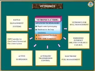
VETRONICS. VETRONICS (CVRDE). BATTLE MANAGEMENT SYSTEMS. VETRONICS FOR HULL MANAGEMENT. ADVANCED TECHNOLOGIES Rapid control prototyping. Hardware in the loop simulation. . Environmental Standards. EMI / EMC Compliance.

Environmental Standards. EMI / EMC Compliance
E N D
Presentation Transcript
VETRONICS VETRONICS (CVRDE) BATTLE MANAGEMENT SYSTEMS VETRONICS FOR HULL MANAGEMENT • ADVANCED TECHNOLOGIES • Rapid control prototyping. • Hardware in the loop • simulation. • Environmental Standards. • EMI / EMC Compliance EMBEDDED INTERNET (MIL STD 1553B) BUS / CAN BUS DSP Controller for Gun Control System and Fire control system ACTIVE SUSPENSION AUTOMATIC TRANSMISSION CONTROL ELECTRONIC FUEL MANAGEMENT
In – Vehicle Networking For Armoured Fighting Vehicles Integrated Fire Control System B M S Gunner’s Controls/ Display Gunner’s Primary Sight Commander’s Independent Thermal Viewer Turret Mission Computer Commander’s Controls/Display Unit ENHANCED SLIP RING 1553B DATA BUS Multi Sensor Suite Digital Electronics Control Unit Hull Power Distribution Unit Position Navigation System Driver’s Integrated Display Hull Mission Computer
Engine HULL ELECTRICAL SYSTEM OF AFVs Instrument Panel L. H Instrument Panel R. H Gear Selector To Lighting Equipment Electronic Control Box Engine Control Junction Box Driver’s Switch Board Fuel Pump Control Box To Fuel Pumps Generator and Regulator 24V / 400 AH Battery Master Relay Box Transmission
SYSTEM CONFIGURATION OF VETRONICS FOR HULL MANAGEMENT TERMINATOR TERMINATION AT TURRET DUAL REDUNDANT MILSTD 1553B BUS RBJ BUS COUPLER BUS COUPLER BUS COUPLER BUS COUPLER BUS COUPLER BUS COUPLER TCP / IP COMMUNICATION FOR SYNCHRONIZATION HANDLER TCP / IP COMMUNICATION FOR SYNCHRONIZATION HANDLER Pentium Intel Mobile Module MIL BUS ACE Pentium Intel Mobile Module MIL BUS ACE HULL CONTROLLER (STANDBY) pSOS DISPLAY CONTROLLER (STANDBY) pSOS DISPLAY CONTROLLER (ACTIVE) pSOS HULL CONTROLLER (ACTIVE ) pSOS IDE & DEBUG DRIVER’S DUPLICATING DISPLAY IDE & DEBUG IDE & DEBUG IDE & DEBUG MUX MUX SERIAL SERIAL COMMUNICATION ENGINE CONTROL ENCLOSURE ELECTRO LUMINESCENT FLAT PANEL TOUCH SCREEN DISPLAY GSL DRIVER’S INSTRUMENT PANEL Hard Switches FROM/TO POWER PACK Master Key Switch Pre Glow Start Emergency start Start lock Deep fording APU ON Emergency shutdown
Functional Requirements • Direction Selection. • Gear selection in manual mode and auto mode. • Automatic upshift / downshift in both modes. • Steering in motion, pivot turn and neutral turn. • Retarder operation. • Lockup engagement and disengagement. • Safety features. • Starting system, Fuel injection System. • Generating System. • Gear sensing control for transmission • override. • Braking system. • Shutdown system. • Control functions for Engine Operation. • Automatic Transmission Control • Lighting Control • Integrated Fuel Level Monitoring System for all tanks including Nose-fuel Tank. • Overall reduced re-action time • Flexibility • Economization of space • Processor based control for the complete Hull Electrical System • C4I Capability via • MIL STD 1553B Bus • Data logging • Capabilities • BITE Capabilities • Dual Redundancy • Excellent Man-Machine Interface through appealing graphics and touch buttons • Access of extensive data base on-line via multiple page set-up Driver’s Duplicating Display
SOFTWARE - VETRONICS C Language Application Software pSOS Engineering Software • Transmission control logic for manual and auto mode. • Engine control logic. • Avoidance of dry run of fuel pumps. • Monitoring of Brake Motor fluid and pressure levels. • A comprehensive display / MMI for the driver in both the cabin and head out positions. • Emergency management to take care of failures at various levels within the system. • Dual redundancy at the controller level. • BITE mode. • Integrated fuel level monitoring of all tanks including Nose fuel tank. • Real Time Operating system (RTOS) • General Purpose Monitor.(GPM). • Digital Input/ Output handler. • Analog Input Handler. • MIL STD 1553 Handler • Serial link Handler 1 (Duplicating Display) • Serial link Handler 2 (Touch panel) • Serial link Handler 3 (TCP/IP) • Serial link Handler 4 ( Debug) • Diagnostics and Health Reporting. • Fault Handler. • Software utilities ( disk drive and printer) • Integrated fuel monitoring of all tanks including nose fuel tank.
BLOCK DIAGRAM OF AUTOMATIC TRANSMISSION CONTROLLER VEHICLE SPEED SENSOR SPEED MEASUREMENT CIRCUIT TRANSMISSION ASSEMBLY ENGINESPEED SENSOR S4 MICROPROCESSOR BASED CONTROLLER O P T O I C S I O R L C A U T I O T R O P T O I C S I O R L C A U T I O T R S3 1 1 S2 2 2 S1 3 3 SF GEAR SELECTOR UNIT SR 4 4 SP F F SLU SA R R DISPLAY SD P P SB N N SC SRE ACCELERATOR PEDAL BRAKE PADEL RS232 TO PC FOR DIAGNOSTICS DRIVER’S CONTROL PANEL STEERING HANDLE PARKINGBRAKE
GEAR SHIFT DIAGRAM OF TRANSMISSION CONTROLLER ENGINE SPEED (rpm) 3083 Engine rpm 3rd GEAR 1st GEAR 2nd GEAR 2916 65.5 km/hr 4th GEAR 17.7 km/hr 34.85 km/hr 2400 52.46 km/hr 30.64 km/hr 15.2 km/hr 45.3 km/hr 28.29 km/hr 2000 27.83 km/hr 41.9 km/hr 39.07 km/hr LU Clutch ON KD ON LU Clutch OFF LU Clutch ON KD OFF LU Clutch OFF 1000 OUTPUT SPEED (rpm) 0 500 1500 1000 2000 0 VEHICLE SPEED (Km/hr) 35 60 10 15 20 25 30 40 55 65 45 5 50
50 1200 Engine Indicator 123456 0 2400 123456 100 0 Engine RPM Vehicle Speed (Km/Hr) Maintenance 5 1670 Shut Down 0 2.5 110 1000 Start 270 1 90 5000 Transmission Indicator 0 180 Coolant Temp .((C) Fuel (Ltrs.) Oil Pressure (Bar) Gun Position Deep Fording Fault Status INTEGRATED TOUCH SCREEN DISPLAY
VETRONICS MODULES Engine RTU Engine RTU Simulator Simulator Drivers RTU Drivers RTU Drivers Inst. Panel Drivers Inst. Panel Engine Control Enclosure Engine Control Enclosure
Engine starting logic viz. • Normal start through RTUs. • Electrical start through conventional • push button (stand by). • Emergency start. • Engine shut down logic viz. • Normal shut down. • Emergency shut down. • Automatic shut down. • Transmission control logic viz. • Direction Selection. • Gear Selection. • Safety features. PERFORMANCES VALIDATED • Control of fuel pumps. • Automatic operation of Bilge pumps. • Lighting control logic. • Monitoring of fuel level in various fuel tanks. • Auto run of the hull • Redundancy function of RTUs. • Data logging / BITE capabilities. • Environmental test on the reduced set. • EMI/EMC test on the reduced set.
Integration of all subsystem of a tank via MILSTD1553B Bus. Total turret Management & Hull Management. Open system architecture. Fast Ethernet Bus - video data link between crew stations. VETRONICS AND THE FUTURE Robust Operating system pSOS caters for entire software load of Armoured Fighting Vehicles. Active matrix LCDs for crew cockpit
CONCLUSION Future Tank would be “A Digital Vehicle”. The software making the ultimate digital difference.