Download
1 / 21
250 likes | 784 Views
Chapter 14: Forging of Metals. 14.1 Introduction. Forging: a Process in which the work-piece is shaped by compressive forces applied through various dies and tools. Typical forged products: bolts, rivets, connecting rods, shafts for turbines, gears, hand tools, etc...

E N D
14.1 Introduction • Forging: a Process in which the work-piece is shaped by compressive forces applied through various dies and tools. • Typical forged products: bolts, rivets, connecting rods, shafts for turbines, gears, hand tools, etc... • Figure 14.3 shows a part made by 3 different processes: (a) casting, (b) machining, (c) forging
14.1 Introduction • Cold forged parts have good surface finish and dimensional accuracy. • Hot forging requires smaller forces, but it produces dimensional accuracy and surface finish that are not as good as in cold forging.
14.2 Open die forging • Most open-die forgings generally weigh 15-500 Kg, forgings as heavy as 275 tons have been made. • Sizes may range from very small parts (nails, pins, and bolts)up to 23 m for ships shafts. • Upsetting or flat-die forging (Fig. 14.3): The die surfaces in open-die forging may have simple cavities, to produce relatively simple forgings.
14.2 Open die forging Figure 14.3: (a) Ideal deformation of a solid cylindrical specimen compressed between flat frictionless dies, an operation known as upsetting. (b) Deformation in upsetting with friction at the die-workpiece interfaces. Note barrelling of the billet caused by friction.
14.2 Open die forging • Barreling is caused primarily by frictional forces at the die-work-piece interfaces that oppose the outward flow of the materials at these interfaces. Barreling can be minimized by using an effective Lubricant. • Barreling can also occur in upsetting hot work-pieces between cold dies. The material at and near the interfaces cools rapidly, while the rest of the work-piece remains relatively hot. Thus, the material at the ends of the work-piece has higher resistance to deformation than the material at its center. Consequently, the central portion of the work-piece expands laterally to a greater extent than do its ends. • Barreling from thermal effects can be reduced or eliminated by using heated dies.
14.2 Open die forging -cogging • Cogging (drawing out): an open-die forging operation in which thickness of a bar is reduced by successive forging steps at specific intervals. Because contact area per stroke is small, a long section of a bar can be reduced in thickness without requiring large forces or machinery
14.2 Open die forging -cogging Figure 14.4: (a) Schematic illustration of a cogging operation on a rectangular bar. Blacksmiths use a similar procedure to reduce the thickness of parts in small increments by heating the workpiece and hammering it numerous times along the length of the part. (b) Reducing the diameter of a bar by open-die forging; note the movements of the die and the workpiece. (c) The thickness of a ring being reduced by open-die forging.
14.2 Open die forging • The forging force, F, in an open-die forging operation on a solid cylindrical piece: • Yf: flow stress of the material, stress required to continue plastic deformation of the work-piece at a particular true strain. • µ :coefficient of friction, • r andh: radius and height of the work-piece • example
14.2 Open die forging • Example14.1: A solid cylindrical slug made of 304 stainless steel is 150 mm in diameter and 100 mm high. It is reduced in height by 50% at room temperature by open-die forging with flat dies. Assuming that the coefficient of friction is 0.2, calculate the forging force at the end of the stroke.
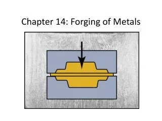
14.3 impression-die and closed-die forging • In impression-die forging, the work-piece acquires the shape of the die cavities while being forged between two shaped dies (Fig. 14.5). • The thin flash cools rapidly, and because of its frictional resistance, it subjects the material in the die cavity to high pressures, thereby encouraging the filling of the die cavity.
14.3 impression-die and closed-die forging • FIGURE I4.5 (a) through (c) Stages in impression-die forging of a solid round billet. Note the formation of flash, which is excess metal that is subsequently trimmed off. (d) Standard terminology for various features of a forging die
14.3 impression-die and closed-die forging • Pre-forming processes, such as fullering and edging (Figs.14.7b and c), are used to distribute the material into various regions of the blank. • In fullering material is distributed away from an area. • In edging, it is gathered into a localized area. • The part is then formed into the rough shape of a connecting rod by a process called blocking, using blocker dies. • The final operation is the finishing of the forging in impression dies that give the forging its final shape. The flash is removed later by a trimmingoperation.
14.3 impression-die and closed-die forging • The blank is placed on the lower die and, as the upper die begins to descend, the blank’s shape gradually changes, as is shown for the forging of a connecting rod in fig. 14.7a.
14.3 impression-die and closed-die forging • The forging force, F, required to carry out an impression-die forging operation can be estimated from the formula F = KYfA where K is a multiplying factor obtained from Table 14.2, Yf is the flow stress of the material at the forging temperature, and A is the projected area of the forging including the flash.
14.3 impression-die and closed-die forging • In true closed-die or flash-less forging ,flash does not form and the work-piece completely fills the die cavity. Consequently, the forging pressure is very high, • Undersize blanks prevent complete filling of die cavity. • Oversize blanks generate excessive pressures and may cause dies to fail.
14.3.1 Precision forging • In order to reduce the number of additional finishing operations required-hence the cost-the trend has been toward greater precision in forged products (net-shape forming). • Special dies produce parts having greater accuracies than those from impression die forging and requiring much less machining. • Process requires higher capacity equipment because of greater forces required to obtain fine details on part. • Precision forging requires special and more complex dies, precise control of billet’s volume and shape, accurate positioning of the billet in die cavity, and hence higher investment. However, less material is wasted, less subsequent machining required.
14.4 Various Forging Operations- Coining • The slug is coined in a completely closed die cavity. • In order to produce fine details the pressures required can be as high as 5 or 6 times the strength of the material. • Lubricants cannot be applied in coining, because they can become entrapped in the die cavities, and being incompressible, prevent the full reproduction of die surface details. • Coining process is also used with forgings and with other products, to improve surface finish and to impart the desired dimensional accuracy. This process, called sizing, involves high pressures, with little change in part shape during sizing. Figure 14.10: Schematic illustration of the coining process
14.4 Various Forging Operations- Heading • Heading: upsetting operation usually performed at end of round rod or wire to produce a larger x-section. • Typical products are nails, bolt heads, screws, rivets, and various other fasteners(Fig. 14.11). FIGURE 14.11: (a) Heading operation to form heads on fasteners, such as nails and rivets. (b) Sequence of operations used to produce a typical bolt head by heading.
14.4 Various Forging Operations- Heading • Rules for upset forging: • Max Length of unsupported metal that can be upset in one blow without buckling: 3 times the diameter of bar. • lengths of stock greater than 3 times diameter may be upset successfully such that the diameter of the cavity is no more than 1.5 the diameter of the bar.