Fibre Optic Sensors at Accelerators – Considerations and Pitfalls
460 likes | 708 Views
Fibre Optic Sensors at Accelerators – Considerations and Pitfalls. Jochen Kuhnhenn. Fibre Optic Sensors at Accelerators Overview. Radiation effects in optical fibres Radiation detection with optical fibres Fibre-optic beam-loss monitors Fibre-optic integrating dosimeters

Fibre Optic Sensors at Accelerators – Considerations and Pitfalls
E N D
Presentation Transcript
Fibre Optic Sensors at Accelerators – Considerations and Pitfalls Jochen Kuhnhenn
Fibre Optic Sensors at AcceleratorsOverview • Radiation effects in optical fibres • Radiation detection with optical fibres • Fibre-optic beam-loss monitors • Fibre-optic integrating dosimeters • Fibre optic temperature and strain sensors at accelerators
Introduction of radiation effects group at Fraunhofer INTBackground of experience Fraunhofer Locations in Germany • Investigation of radiation effects in electronic and opto-electronic components since 25 years • Operating several dedicated irradiation facilities(Co-60, Neutrons, X-Ray, …) • Supports manufacturers and users (space, accelerators, medicine, nuclear facilities, …) • Specialised knowledge led to the development of several unique radiation detection systems • Thanks to our collaborators: • DESY (M. Körfer, K. Wittenburg) • HMI (F. Wulf, W. Goettmann) • BESSY (J. Bahrdt) • CERN (T. Wijnands, D. Ricci, Elisa Guillermain)
Fibre Optic Sensors at AcceleratorsOverview • Radiation effects in optical fibres • Radiation detection with optical fibres • Fibre-optic beam-loss monitors • Fibre-optic integrating dosimeters • Fibre optic temperature and strain sensors at accelerators
3 1 2 Radiation effects in optical fibresOverview • Throughout this presentation “Radiation” means ionising radiation(X-rays, g-rays, particles) • Radiation changes all properties of optical fibres, but some are only relevant at high doses with small (practical) influence • Change of refractive index • Change of bandwidth • Change of mechanical properties (e.g. dimension, strength) • Radiation-induced luminescence light • Most important effect in this context Cherenkov radiation • Most obvious and disturbing effect is an increase of their attenuation (RIA) • Strongly depending on actual fibre and radiation environment
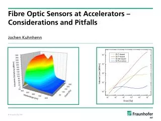
Parameter dependencies of RIAExperimentally observed effects • Manufacturing influences • Fibre type (Single mode, graded index, step index) • Doping of core/Doping of cladding(for SM fibres) • Preform manufacturer and used processes • Core material manufacturer • OH Content • Cladding core diameter ratio (CCDR) • Coating material • Drawing conditions • Operation conditions • Wavelength • Light power • Launch conditions • Environment • Total dose • Dose rate • Annealing periods / Duty cycle • Temperature In combination with each other: Differences of many orders of Magnitude possible!
Example of dependenciesCore doping effects (~830 nm) • What does that mean for injected light of 1 mW: • Wavelength: ~830 nm • Fibre length: 100 m • Pure silica fibre: 0.89 mW • F-doped fibre: 0.17 mW • Ge-doped fibre: 310-6 mW • P-doped fibre: 10-200 mW
Radiation effects in optical fibres: Short summary • Huge (orders of magnitude) differences between different fibres, environments and operation conditions • Reliable and application specific radiation testing requires experience • Difficult to transfer or even compare results of different tests • No predictive theoretical model available, some extrapolations possible • There are only very few “rules of thumb” you can trust! • Carefully review sales information, question simplified statements
Fibre Optic Sensors at AcceleratorsOverview • Radiation effects in optical fibres • Radiation detection with optical fibres • Fibre-optic beam-loss monitors • Fibre-optic integrating dosimeters • Fibre optic temperature and strain sensors at accelerators
Main advantages of optical fibres as radiation sensorsGeneral and for accelerator applications • Immune against external electro-magnetic-fields • Do not disturb external high precision magnetic fields, e.g. in the undulator section of free electron lasers • Environmental conditions (temperature, vacuum, …) usually no major problem • Capable of monitoring extended areas • Extremely small sensors: diameter of much less than 1 mm
Introduction to light guiding in step-index optical fibres • Total reflection of light if angle below critical value • Different possible light paths cause dispersion • Parameters of interest: • Difference of refractive index between core and cladding • Launch conditions into fibre (angle of incident)
Wavelength dependencies for Cherenkov detection • Light guiding and signal detection dependent on the following contributions • Fibre attenuation as a function of wavelength • Photon efficiency of selected photodetector • Wavelengths of interest: • 400 nm to 800 nm
Detection efficiency of fibre optic Cherenkov sensorInfluence of fibre length
Detected signals as a function of fibre length • Decrease of signal due to (intrinsic) attenuation in the fibre • Comparable signals at different locations if events are within ~20 m • BUT: No influence of radiation-induced attenuation considered
Photon collection efficiency • Full light cone has to be taken into account • Possibility for grazing incident and spiral light propagation G. Anzivino et. al., NIMA(357)380
Meas. Sci. Technol. 18 (2007) 3257–3262 Lots of 3-D simulation results CERN-ATS-2011-066 Vol. 45, No. 36 APPLIED OPTICS 9151 Radiat. Phys. Chem. Vol. 41, pp. 253, 1993 NIM A 357 (1995) 380 P. Gorodetzky et. al., NIMA(361)161
NIM A 357 (1995) 380 NIM A 360 (1995) 237 NIM A 357 (1995) 369 90° DOI: 10.1063/1.1570945 NIM A 367 (1995) 271 Experimental angular dependence
Installation at accelerators • Version 1: PMT looks upstream Beam Beam pipe PMT • Version 2: PMT looks downstream • Advantages: Higher signal due to better geometry Beam Beam pipe PMT • Advantages: • Better resolution (“velocity” for time scaling: 0.4 c) • Always correct order of events recorded in PMT
Selection of a Cherenkov fibreGeneral considerations • Manufacturer: • Really know who has drawn the fibre, who has made the preform • Selecting the fibre type: • Established recommendation:High OH pure-silica core step-index fibre with F-doped silica cladding • Alternatives might become more interesting soon (see below) • Selecting the core diameter: • The larger the core, usually the higher the price • Minor dependence of bandwidth and core diameter (if any) • Selecting the NA: • Compromise between efficiency and bandwidth: Dt ≈ L/(2nc)*(NA)² • Shield ambient light with buffer, e.g. black nylon Perform dedicated, meaningful radiation tests!
Examples of uses at accelerators: DELTA • Installation at DELTA (Uni Dortmund) • Injection efficiency was poor DELTA Dortmund
Examples of results at DELTA: Injection efficiency Kuhnhenn, doi: 10.1117/12.624039
Radial arrangement of 4 sensor fibres • Asymmetric signals can detect directed losses Fibres Beam pipe
Results of the Cherenkov system at FLASH undulators F. Wulf, 2009 IEEE Nuclear Science Symposium
Other examples: University Lund and DESY Zeuthen Grabosch, SEI Herbst 2007 J. Bahrdt, FEL 2008
Advantages of fibre optic Cherenkov detectors • “Real time” commissioning and optimisation • Prevents damages due to high undetected beam losses • Simple to install and covers whole accelerator areas • Proven and used routinely at several installations
Considerations for fibre optic Cherenkov detectorsSelection between “equal” pure-silica core fibres • At 850 nm • At 660 nm
Considerations for fibre optic Cherenkov detectorsNew optical fibres with better (UV) radiation resistance • Solarisiation-optimised optimised fibres • F-doped core optical fibres 365 nm 214 nm 551 nm 310 nm A. Alessi, presented at RADECS 2011 DOI: 10.1109/TNS.2010.2042615
Fibre Optic Sensors at AcceleratorsOverview • Radiation effects in optical fibres • Radiation detection with optical fibres • Fibre-optic beam-loss monitors • Fibre-optic integrating dosimeters • Fibre optic temperature and strain sensors at accelerators
Fibre optic dosimetryHistorical perspective S. Kronenberg and C. Siebentritt, Nucl.Instr.Meth. 175 (1980) 109-111
Fibre optic dosimetryA long way from the idea to the real application • Gaebler, 1983:„... fibres exhibit properties, which are excellent suited for their application as radiation detectors.“ • Lyons, 1985:„... P-doped fibers ... might be ... suitable for ... dosimetry.“ • Henschel, 1992:„... radiation induced loss ... has been investigated with respect to the suitablility for radiation dosimetry purposes.“ • Borgermans, 1999:„The ... fibre may be used for dosimetry applications ...“ • West, 2001:„ response of P-doped fibres is reviewed ... [for] their possible use in dosimetry.“ • van Uffelen, 2002:„Feasibility study for distributed dose monitoring ...“
0.6 Irradiation Annealing (Ge+P)-doped 0.5 0.4 0.3 Induced Loss [dB/m] 0.2 0.1 Ge-doped 0.0 0 1000 2000 3000 4000 5000 6000 Time [s] Fibre optic dosimetryPrinciple: Measuring RIA in P-doped optical fibres • Properties of radiation induced attenuation (RIA) in P-co-doped optical fibres: • Strong effect High sensitivity • Linear dose response Quantitative results • Slow annealing Dose rate independence • High reproducibility Only one calibration per fibre sample necessary
2 0.972 10 × A [dB/m] = 0.0369 (D [Gy]) l =678 nm 1 10 0 10 -1 10 Induced Loss [dB/m] -2 10 Fit -3 10 0.00618 Gy/min 0.0624 Gy/min 2.175 Gy/min -4 10 9.606 Gy/min 69.342 Gy/min -5 10 -4 -3 -2 -1 0 1 2 3 4 10 10 10 10 10 10 10 10 10 Dose [Gy(SiO )] 2 Fibre optic dosimetryCalibration and dose rate dependency • One fit covers all dose rates(>4 orders of magnitude difference) • Nearly lineardose-attenuation function • Saturation of induced attenuation only above ~1000 Gy • Calibration for this fibre: • D[Gy] A[dB/m] * 27
Accumulated dose since 2002-03-21 compared to TLD measurements Easter Dose [Gy] Date Exemplary results for power meter measurements at TTF1
Fibre optic dosimeters based on RIA measurements • Simple principle requires sophisticated measurement techniques for reliable and accurate data • Main advantages: • Integrating (even if no readout takes place) • Small sensor size (< 0.5 mm if necessary) • Quantitative dose data(tested for different dose rates and radiation energies) • High sensitivity (~ some 10 mGy/hour)
Fibre Optic Sensors at AcceleratorsOverview • Radiation effects in optical fibres • Radiation detection with optical fibres • Fibre-optic beam-loss monitors • Fibre-optic integrating dosimeters • Fibre optic temperature and strain sensors at accelerators
Using Fibre-Bragg-Gratings in radiation environmentsPrinciple • Applications for FBGs: • Temperaturesensors • Strainsensors • „Mirrors“ for fibre lasers • Advantages: • Distributedsystem • Passive Light source Transmittedspectrum l = 2 n L Reflectedspectrum g Change of refractiveindex due to radiation
CLPG; ~5000 pm Very sensitive radiation sensor UV FBG; 100 pm High dose radiation sensor DlB [pm] Fs-IR FBG; 5 pm Radiation „hard“ temperature and strain sensor Dosis [kGy] Radiation effects in Fibre-Bragg-GratingsDifferences in manufacturing method and used fibre
Using other fibre optic sensors in radiation environments • The above mentioned advantages of fibre optic sensors are attractive for other measurements at accelerators • Widely used fibre optic sensors in conventional environments • Strain (bridges, buildings, tunnels, …) • Temperature (tunnels, dams, …) • Moisture (tunnels, dams, …) • Application in radiation environments can be challenging
Example: Fibre optic temperature sensor • Principle: • Similar to OTDR measurement but not the original backscattered signal is analysed but two spectrally shifted peaks (stokes and anti-stokes) • Temperature information is derived by comparing the amplitudes of the two signals • Problem in radiation environment: • Radiation induced loss strongly depends on wavelength One peak (at lower wavelength) gets more attenuated than the other on (at higher wavelength) • Radiation leads to apparent temperature change
Last slide • Overview of radiation effects in optical fibres was given • This presentation introduced different radiation sensors using optical fibres • Cherenkov systems • Power meter systems • Fibre-Bragg-Gratings • Finally some other aspects of using optical fibres at accelerators were presented, such as using optical fibre sensors in radiation environments • Unfortunately not covered • Telecommunication applications in radiation environments (e.g. CERN) • Stimulated annealing of radiation induced attenuation
Thank you for your attention! • Contact: • Jochen KuhnhennFraunhofer INTAppelsgarten 253879 Euskirchen • Email: jochen.kuhnhenn@int.fraunhofer.de • Tel.: +49-2251-18 200Fax: +49-2251-18 38 200