Biomedical Sensors
2.67k likes | 7.16k Views
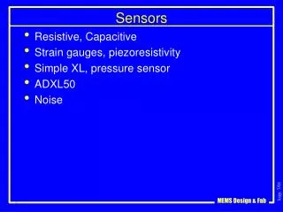
Biomedical Sensors. Instrumentation System Sensor characteristics Physical Sensors . Announcements. On Wednesday we continue the two groups (1:30pm and 3pm). You are responsible for running the experiments! Webct has a suggested format for lab reports. . Sensors. Electrical Input.

Biomedical Sensors
E N D
Presentation Transcript
Biomedical Sensors Instrumentation System Sensor characteristics Physical Sensors
Announcements • On Wednesday we continue the two groups (1:30pm and 3pm). • You are responsible for running the experiments! • Webct has a suggested format for lab reports.
Sensors Electrical Input Physical parameter Electrical Output Physical Output Sensor is a Transducer:What is a transducer? A device which converts one form of energy to another e.g. Piezoelectric: Force -> voltage Voltage-> Force Actuators
Temperature Accelerometers Pressure sensors Chemical Biochemical Resistance _____________ _____________ _____________ Galvanic skin test Glucose detection Heart rate Vital signs Cochlear implants Retinal implant Cortical implant Health monitoring _____________ _____________ Biomedical sensors: examples and applications
Performance Characteristics 1/3 • Transfer Function: • The functional relationship between physical input signal and electrical output signal. Usually, this relationship is represented as a graph showing the relationship between the input and output signal, and the details of this relationship may constitute a complete description of the sensor characteristics. • Sensitivity: • Relationship between input physical signal and output electrical signal. • The ratio between a small change in electrical signal to a small change in physical signal. As such, it may be expressed as the derivative of the transfer function with respect to physical signal. Typical units : Volts/Kelvin. A Thermometer would have "high sensitivity" if a small temperature change resulted in a large voltage change. • Span or Dynamic Range: • The range of input physical signals which may be converted to electrical signals by the sensor. Signals outside of this range are expected to cause unacceptably large inaccuracy. This span or dynamic range is usually specified by the sensor supplier as the range over which other performance characteristics described in the data sheets are expected to apply.
Precise Accurate Performance 2/3 • Accuracy: • Generally defined as the largest expected error between actual and ideal output signals. Sometimes this is quoted as a fraction of the full scale output. For example, a thermometer might be guaranteed accurate to within 5% of FSO (Full Scale Output) • Precision: • How repeatable the sensor is. Uniformity in reproducing one result. Depends on method. Here there is no comparison to a standard, to a particular “ideal” result. • Hysteresis: • Some sensors do not return to the same output value when the input stimulus is cycled up or down. The width of the expected error in terms of the measured quantity is defined as the hysteresis. Typical units: Kelvin (for temperature sensors) or % of FSO • Nonlinearity (often called Linearity): • The maximum deviation from a linear transfer function over the specified dynamic range. There are several measures of this error. The most common compares the actual transfer function with the ‘best straight line', which lies midway between the two parallel lines which encompasses the entire transfer function over the specified dynamic range of the device. This choice of comparison method is popular because it makes most sensors look the best.
Performance Characteristics 3/3 • Noise: • All sensors produce some output noise in addition to the output signal. The noise of the sensor limits the performance of the system based on the sensor. Noise is generally distributed across the frequency spectrum. Many common noise sources produce a white noise distribution, which is to say that the spectral noise density is the same at all frequencies. Since there is an inverse relationship between the bandwidth and measurement time, it can be said that the noise decreases with the square root of the measurement time. • Resolution: • The resolution of a sensor is defined as the minimum detectable signal fluctuation. Since fluctuations are temporal phenomena, there is some relationship between the timescale for the fluctuation and the minimum detectable amplitude. Therefore, the definition of resolution must include some information about the nature of the measurement being carried out. • Bandwidth: • All sensors have finite response times to an instantaneous change in physical signal. In addition, many sensors have decay times, which would represent the time after a step change in physical signal for the sensor output to decay to its original value. The reciprocal of these times correspond to the upper and lower cutoff frequencies, respectively. The bandwidth of a sensor is the frequency range between these two frequencies.
Chemical Sensors (Biosensors) Biosensors produce an output (electrical) which is proportional to the concentration of biological analytes. A typical biosensor Signal Conditioning Analyte Biological Detection Agent Transducer
Biosensing Principles Chemical Sensing • => Neurochemical sensor for Dopamine, Nitric Oxide, etc. • => Pulse oximeter • => Accelerometer, microphone • => Implanted rectal probe, pacemaker • Electrochemical • Potentiometric • Amperometric • FET based • Conductometric • Optical • Piezoelectric • Thermal Direct electrochemical transduction Absorption, fiber optic transmission Chemical binding changes the resonance property such as frequency Thermal/temperature response to chemical reaction
Electrochemical Sensors Potentiometric : These involve the measurement of the emf (potential) of a cell at zero current. The emf is proportional to the logarithm of the concentration of the substance being determined. Amperometric : An increasing (decreasing) potential is applied to the cell until oxidation (reduction) of the substance to be analyzed occurs and there is a sharp rise (fall) in the current to give a peak current. The height of the peak current is directly proportional to the concentration of the electroactive material. If the appropriate oxidation (reduction) potential is known, one may step the potential directly to that value and observe the current. Conductometric. Most reactions involve a change in the composition of the solution. This will normally result in a change in the electrical conductivity of the solution, which can be measured electrically.
pO2: Historical background • Bare metal electrodes: in use since 1923 • Davies & Brink (1943)1: the recessed electrode • Clark (1953 and 1956)2: membrane covered cathode and anode next to each other • From R.S.C. Cobbold, “Transducers for Biomedical Measurements”, 1974. 1 W.L.Nastuk, “Physical Techniques in Biological Research”, 1962. 2 L.C. Clark, Trans. Am. Soc. Artif. Internal Organs, 2, 41, 1956.
Biomed-Applications • Brain – ischemia, epilepsy • Heart – anoxia, hypoxia, drug effects • Muscle – contraction coupling, K+ channels • Tumors – rate of success of PDT* • Eye – cornea, free radicals • Others: skin, blood, nerves, liver, etc. * PDT = photodynamic therapy. Cancer therapy based on the accumulation of a photosensitizing drug in malignant tissues.
1 Fundamentals of membrane-covered polarographic oxygen electrodes 1 From I.Fatt, “Polarographic Oxygen Sensor”, 1976
Simplified model for an metabolic active tissue Assumptions: • Q, D and k are independent of P; • No salting out in the bathing solution; • Homogeneous tissue; • No poisoning of the membrane interface; • Q and k areindependent of temperature. After Takahashi et al., J.Gen.Physiol., 50,317, 1966; and Freeman, J. Physiol., 225, 15, 1972.
Active area with sensor array Petri dish 5 mm Fabricated device Main issues: • reproducibility (membrane thickness and overall performance); • reusability; • temperature control; • encapsulation for cell culture; • cleaning; • cost. Objective: metabolic activity monitoring in HL-1 cultures. Active area Integrated oxygen sensor array
7 6 5 4 3 2 1 Modified Clark-type oxygen sensorProcessing sequence1 (brief) • (layers 1-4): substrate, oxidation, metal, passivation. • (layer 5): Nafion:PVP. • Nafion 5% in alcohol is mixed to PVP (4:1). • Nafion:PVP is deposited on the arrays, and cured at 140oC for 20h. • (layer 6): PTFE deposition. • Oxygen plasma for 5min (1Torr, 450sccm O2, 500W) • Pulsed plasma for 90min (1.3Torr, 100sccm HFPO, 2.3sccm Ar, 0.7W/cm3 peak) • (layer 7): encapsulation: epoxy or PDMS. • Either epoxy (Supreme 42HT/T) or PDMS (Sylgard® 184). 7. Epoxy or PDMS 6. PTFE 5. Nafion:PVP 4. Nitride 3. Cr/Au 2. Oxide 1. Si 1 From G.W. McLaughlin et al., Transducers’01, 2:1692, 2001.
20mm 40mm HL-1 cells on PTFE coated arrays • HL-1 cultured at 50 or 100k cells/dish; • Experiments performed on 3rd or 4th div; • Perfusing medium: Claycomb (no norepinephrine); • Drug application protocol depends on time course of action;
Experimental setup thermometer DO meter/ DO control outflow inflow heater cells DIP package potentiostat laptop with daq board Perfusing media
Mimicking anoxia on HL-1 cells Coverslip on tissue
Response to verapamil Response of HL-1 cells to verapamil (10µg/L) application and washout. 020306_sample011203_4_16
Nifedipine application • Metabolism evaluation in HL-1 cultures • Dissolved oxygen measured in control cultures (Claycomb medium). • Metabolic inhibitors: nifedipine, cyanide, verapamil. • Enhancing metabolism: thyroxine, isoproterenol. Response of HL-1 cells to nifedipine (1µM) application and washout.
Flow cytometer Physical Sensors • Blood flow/blood pressure • Impact, acceleration • Surgical forceps to measure force applied • Airbag • Body temperature PCR
Biomedical Physical Sensors • Design circuit to use Hg strain gauge to detect chest movement/respiration • Pacemaker • Airbag What application of a bladder pressure sensor can you think of?
Resistive Sensors - Potentiometers Translational and Rotational Potentiometers Translational or angular displacement is proportional to resistance. Taken from www.fyslab.hut.fi/kurssit/Tfy-3.441/ luennot/Luento3.pdf
Resistive Sensors - Strain Gages Resistance is related to length and area of cross-section of the resistor and resistivity of the material as By taking logarithms and differentiating both sides, the equation becomes piezoresistance Dimensional Strain gage component can be related by poisson’s ratio as
Resistive Sensors – Strain Gage Gage Factor of a strain gage • Think of this as a Transfer Function! • Input is strain • Output is dR G is a measure of sensitivity • Put mercury strain gauge around an arm or chest to measure force of muscle contraction or respiration, respectively • Used in prosthesis or neonatal apnea detection, respectively
Resistive Sensors - Strain Gages Where can you use it in the body? E.g. prosthetic, or artificial hip/knew? Strain gages are generally mounted on cantilevers and diaphragms and measure the deflection of these. More than one strain gage is generally used and the readout generally employs a bridge circuit.
Strain Gage Mounting • Applications! • Surgical forceps • Blood pressure transducer (e.g. intracranial pressure • Atomic force microscope Taken from http://www.omega.com/literature/transactions/volume3/strain3.html
Vs Rf R+dR R-dR Vo R R Bridge Circuits Wheatstone’s Bridge Real Circuit and Sensor Interface
An interesting application: traffic signal Beach comber! Mine sweeper Inductive Sensors Displacement Sensor Primary Secondary An inductor is basically a coil of wire over a “core” (usually ferrous) It responds to electric or magnetic fields A transformer is made of at least two coils wound over the core: one is primary and another is secondary Inductors and tranformers work only for ac signals
Inductive Sensors - LVDT Linear Variable Differential Transformer LVDT Taken from http://www.icit.es/mediac/400_0/media/DIR_109/lvdt-diagram.jpg An LVDT is used as a sensitive displacement sensor: for example, in a cardiac assist device or a basic research project to study displacement produced by a contracting muscle.
LVDT principle Linear Variable Differential Transformer http://www.icit.es/4655/46122.html
Question: How can I detect small change in capacitance? How does an elevator keypad or certain contact less computer keypads work? Capacitive Sensors Electrolytic or ceramic capacitors are most common e.g. An electrolytic capacitor is made of Aluminum evaporated on either side of a very thin plastic film (or electrolyte)
Capacitive Sensors Other Configurations a. Variable Area Mode b. Variable Dielectric Mode c. Differential Mode
Piezoelectric Sensors What is piezoelectricity ? Strain causes a redistribution of charges and results in a net electric dipole (a dipole is kind of a battery!) A piezoelectric material produces voltage by distributing charge (under mechanical strain/stress) • Different transducer applications: • Accelerometer • Microphone
Piezoelectric Sensors 31 denotes the crystal axis Above equations are valid when force is applied in the L,W or t directions respectively.
Piezoelectric Sensors - Circuitry Capacitor to hold charge Voltage generartor Leakage Resistor The Equivalent Circuit Taken from Webster, “Medical Instrumentation”
Temperature Sensors • Resistance based • a. Resistance Temperature Devices (RTDs) • b. Thermistors • Thermoelectric – Thermocouples • Radiation Thermometry • Fiber Optic Sensor
RTDs RTDs are made of materials whose resistance changes in accordance with temperature Metals such as platinum, nickel and copper are commonly used. They exhibit a positive temperature coefficient. A commercial ThermoWorks RTD probe
Over a small dynamic range a thermistor can be linearized Thermistors Thermistors are made from semiconductor material. Generally, they have a negative temperature coefficient (NTC), that is NTC thermistors are most commonly used. Ro is the resistance at a reference point (in the limit, absolute 0).
Thermocouples Seebeck Effect When a pair of dissimilar metals are joined at one end, and there is a temperature difference between the joined ends and the open ends, thermal emf is generated, which can be measured in the open ends. This forms the basis of thermocouples. In a bimetallic strip, each metal has a different thermal coefficient…this results in electromagnetic force/emf or bending of the metals.
Thermocouples Cooling electronics, camera chips Taken from Webster, “Medical Instrumentation”
Governed by Wien’s Displacement Law which says that at the peak of the emitted radiant flux per unit area per unit wavelength occurs when maxT=2.898x10⁻³ moK Radiation Thermometry Infrared or thermal cameras Taken from http://hyperphysics.phy-astr.gsu.edu/hbase/wien.html#c2
Fiber Optics Most of the light is trapped in the core, but if the cladding is temperature sensitive (e.g. due to expansion), it might allow some light to leak through. -> hence the amount of light transmitted would be proportional to temperature -> since you are measuring small changes in light level, this sensor is exquisitely sensitive. A fiber optic cable
Fiber Optics Based on Total Internal Reflection Taken from http://hyperphysics.phy-astr.gsu.edu/hbase/phyopt/totint.html#c1