Download
1 / 10
100 likes | 127 Views
Explore the design and engineering choices behind the 4-cavity cryomodule at the European Spallation Source (ESS) and the benefits it offers in terms of reduced risk and schedule constraints.

E N D
Optimum cryomodule length at the ESS Wolfgang Hees ESS - leader Accelerator Test Stands 2012-11-07 TTC meeting JLab
The European Spallation Source Lund, Sweden
add. beam line valves: High-beta Cryomodule 2012 design: 4 cavities 2011 design: 8 cavities • concept, design & engineering done by IPN Orsay • based on SNS type space frame
Why 4 cavities per CM ?(and not 8) 4-cavity design based on SNS type is more conservative, requires less design effort and presents less risk to scope, cost and schedule. Availability of infrastructure drives schedule: • 8-cavity cryomodules need very large clean rooms: class 10 /100 (100 m2) + class 1000 (5 world wide ?) • access to DESY or CERN clean rooms is questionable due to overlap of ESS’ schedule with XFEL’s and LHC’s A relatively short machine & small number of CMs results in higher prototyping cost per CM, which should be minimized - and - a very tight schedule demands quick prototyping: only solution is a conservative design.
4 cavity design • It presents a higher heat load because of the additional cold-warm transitions and additional valve boxes & jumper connections. For ESS there is a 10% increase in total heat load. • It induces higher costs for the helium distribution system (valve boxes & jumper connections) • It results in a longer linac. For ESS there is a 14 m increase of the high-β section. • It requires twice the number of units, which might increase production time (not confirmed). • It reduces both technical and project risk. • It is better understood and reduces time for prototyping and pre-series. For ESS there is a projected gain of 2 yrs.
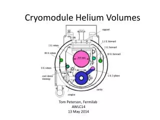
ESS High-beta CM design Like in the SNS design, a spaceframe supports the cold mass inside the vacuum vessel.
ESS High-beta CM design TA6V Each cavity is supported by 2 sets of 4 cross rods to keep the cavity axis aligned with the beam axis and by 2 sets of 2 axial rods for longitudinal positioning.
Conclusions • ESS will build a high-power proton linac by 2019 • our high-β cryomodules will have 4 cavities each • there are downsides (heat load, space) • but the reduction in risk & gain in schedule by extrapolating from a tested design makes this by far the preferred solution • Choice concurred by ESS TAC: “The Committee supports the decision of having only 4 high beta cavities per cryomodule.”
www.ess-scandinavia.eu we will be hiring cryo-engineers