Download
1 / 39
390 likes | 533 Views
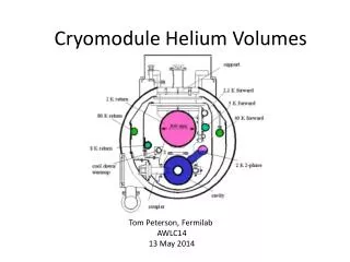
Mechanical studies of the cryomodule. Paulo Azevedo , CERN – TE/MSC 5 th SPL Collaboration Meeting, 26/11/2010. Contents. Introduction Supporting system – Required stiffness Power coupler as support Inter-cavity sliding supports Vacuum vessel design Recent models - comparison

E N D
Mechanical studies of the cryomodule Paulo Azevedo, CERN – TE/MSC 5th SPL Collaboration Meeting, 26/11/2010
Contents • Introduction • Supporting system – Required stiffness • Power coupler as support • Inter-cavity sliding supports • Vacuum vessel design • Recent models - comparison • Assembly Tooling – Required stiffness 5th SPL Collaboration Meeting, 26/11/2010
1. Introduction Calculations carried out with the aim of evaluating possible support solutions for the components of the SPL cryomodule and the SPL test cryostat. 5th SPL Collaboration Meeting, 26/11/2010
1. Introduction Transversal position tolerance of cavities inside cryostat 5th SPL Collaboration Meeting, 26/11/2010
1. Introduction Possible supporting schemes “Standard” supporting scheme Two-support preferrable isostatic (=well defined forces on supports) ...but is cavity straightness enough?? If not... RF coupler (with bellows) Fixed support Invar longitudinal positioner Sliding support External supports (jacks) Inertia beam 5th SPL Collaboration Meeting, 26/11/2010
1. Introduction Possible supporting schemes “Standard” supporting scheme ...add 3rd support becomes hyperstatic (= forces depend on mech. coupling vessel/inertia beam) RF coupler (with bellows) Fixed support Invar longitudinal positioner Sliding support External supports (jacks) Inertia beam 5th SPL Collaboration Meeting, 26/11/2010
1. Introduction Possible supporting schemes Alternative: coupler supporting scheme ...the coupler is also a supporting/aligning element RF coupler + longitudinal positioner + vertical support Intercavity support structure External supports (jacks) 5th SPL Collaboration Meeting, 26/11/2010
2. Supporting system – required stiffness Calculations performed with the aim of estimating the stiffness which the support system (“Standard “supporting solution) of the SPL cavities would have to provide for the string of cavities to be kept inside a certain alignment tolerance. • Beam simply and symmetrically supported on two points, loaded by the weight of the cavities and by its own weight. • Loads are distributed uniformly along the beam • The cavities and the supports are considered to be rigid -maximum beam deflection is a measure of the maximum cavity misalignment. 5th SPL Collaboration Meeting, 26/11/2010
2. Supporting system – required stiffness Required stiffness – different cross sections • L=13 m, mcav=200 Kg, ncav=8 , g=9.8 m/s2 • Stainless steel 304 L: ρ=8000 kg/m3; E=1.93e11 Pa 5th SPL Collaboration Meeting, 26/11/2010
2. Supporting system – required stiffness Third support? – Comparison with 2 supports - Three vertical displacements (simple supports) - Loads remain the same. - One support in the middle of the beam, the other two at a distance of 0.16 L from each end of the beam. 5th SPL Collaboration Meeting, 26/11/2010
3. Power coupler as support Two different support scenarios : 1. cavity supported only by a fixed support on the Power Coupler flange, 2. cavity supported by the PC and by a vertical support on the other extremity of the Helium Vessel. Loads: Weights of the represented parts (1068 N) plus weight of the tuner (147N) Materials: Titanium for the Helium Vessel and Stainless steel for the other parts. These models are previous versions. 5th SPL Collaboration Meeting, 26/11/2010
3. Power coupler as support Max.stress: 650 MPa Max.displacement: 11 mm RF coupler in cantilever Max.stress: 20 MPa Max.displacement: 0.04 mm RF coupler + intercavity guides Total displacement (m), amplification of 1100x von Mises stress (Pa) 5th SPL Collaboration Meeting, 26/11/2010
3. Power coupler as support Coupler supporting scheme Layout Equivalent sketch No - If sag small enough - If strenght OK - isostatic l Yes - couple cavities - hyperstatic inter-cavity guides 5th SPL Collaboration Meeting, 26/11/2010
Conceptual design: 4. Inter-cavity sliding support Scheme of link between cavities: Stainless steel cylinders:length of 420 mm and diameter of 40 mm. 5th SPL Collaboration Meeting, 26/11/2010
4. Inter-cavity sliding support Size of stiffeners increased for better results: Inter cavity support’s stiffness: Frictionless: Sliding and rotation about longitudinal axis allowed Fixed: no sliding, no rotation 2 x E= 193 Gpa ν = 0.31 Φ 40 170 250 5th SPL Collaboration Meeting, 26/11/2010
4. Inter-cavity sliding support Analysis with one He vessel / cavity and two power couplers (double tube): von Mises stress (Pa): in Pascal Max: 67 MPa 5th SPL Collaboration Meeting, 26/11/2010
4. Inter-cavity sliding support Vertical displacement (colour) [m]: in meters Max: 0.097 mm in meters Max: 0.178 mm • Body deformation amplified 300x 5th SPL Collaboration Meeting, 26/11/2010
4. Inter-cavity sliding support Analysis of string of 4 cavities: 5th SPL Collaboration Meeting, 26/11/2010
4. Inter-cavity sliding support Vertical displacement (colour) [m]: Max: 0.12 mm • Body deformation amplified 300x 5th SPL Collaboration Meeting, 26/11/2010
4. Inter-cavity sliding support von Mises stress (Pa): Max: 348 MPa • Different colour scales 5th SPL Collaboration Meeting, 26/11/2010
Three different vessels were modelled with the same thickness and supports. Two different shapes are analysed. All these calculations refer to conceptual designs. A larger diameter may be a requirement for a circular vessel due to assembly. 5. Vacuum vessel design 1. Diameter 1400 3. “U” shape (Radius 510) 2. Diameter 1016 5th SPL Collaboration Meeting, 26/11/2010
5. Vacuum vessel design Different sets of loads were applied: 1. Weight loads: weight of vessel plus loads caused by weight of the string of cavities 2. Pressure loads: external pressure of 1 bar 3. Weight loads plus pressure Weight loads plus pressure: 5th SPL Collaboration Meeting, 26/11/2010
Results: 5. Vacuum vessel design 5th SPL Collaboration Meeting, 26/11/2010
Results: Vertical displacement [m] under external pressure of 1 bar: 5. Vacuum vessel design Max: 0.36 mm • Body deformation amplified 500x 2. Diameter 1016 Max: 4.3 mm • Body deformation amplified 100x 3. “U” shape (Radius 510) 5th SPL Collaboration Meeting, 26/11/2010
Analyses with string of cavities: smaller circular vessel and “U” shape vessel. Weight Loads. 5. Vacuum vessel design Positive but small influence of the stiffness of the string of cavities: 2. Diameter 1016 3. “U” shape (Radius 510) 5th SPL Collaboration Meeting, 26/11/2010
5. Vacuum vessel design Thermal gradient: 10 K difference between top and bottom of vessel (tentative value – a full thermal model should be made, including active cooling of couplers). Thermal gradient: 5th SPL Collaboration Meeting, 26/11/2010
Resume of results and estimation of accumulated deflections 5. Vacuum vessel design 5th SPL Collaboration Meeting, 26/11/2010
New models of the vacuum vessel and power coupler were compared to previous models. 6. Recent models – comparison Previous model New model Main differences: thickness of the helium vessel, not constant in the first case (3 and 5 mm) and constant in the second (5 mm), thickness of the outer and inner walls of the power coupler, as well as the space between them (respectively 1.5, 2 and 4.5 mm for the older version and 2, 1.5 and 1 mm for the new version). 5th SPL Collaboration Meeting, 26/11/2010
Analyses single cavity Analyses string of four cavities cavity 6. Recent models – comparison 5th SPL Collaboration Meeting, 26/11/2010
7. Assembly tooling – Required stiffness Different support scenarios were considered. FE calculations including the string of cavities were performed. Analytical calculations were carried out considering that the support system is comparable to a beam. The length of the beam is 6.8 m for the 4 cavities test cryostat, and the double for the 8 cavities cryomodule. 5th SPL Collaboration Meeting, 26/11/2010
FE analyses of the string of cavities, simplified model and loads: 7. Assembly tooling – Required stiffness • Global view • Section plane view • Fixed inter cavity support (instead of sliding) 5th SPL Collaboration Meeting, 26/11/2010
7. Assembly tooling – Required stiffness Max: 0.09 mm Body deformation amplified 100x Max: 37 mm 10x Max: 11 mm 10x Max: 7.4 mm 10x Max: 5.4 mm Kspring = 20% weight 4 cav. string / 5 mm 10x 5th SPL Collaboration Meeting, 26/11/2010
7. Assembly tooling – Required stiffness In red: von Mises stress values higher than half of the yield strength of stainless steel (~200 MPa): Kspring = 20% weight 4 cav. string / 5 mm 5th SPL Collaboration Meeting, 26/11/2010
7. Assembly tooling – Required stiffness Support: Analytical calculation Loads: Weight of string of cavities and support Material: Structural steel: ρ=7850 kg/m3; E=2e11 Pa 5th SPL Collaboration Meeting, 26/11/2010
7. Assembly tooling – Required stiffness Support: Analyses with the string of cavities; different sizes Rigid Connection 5th SPL Collaboration Meeting, 26/11/2010
7. Assembly tooling – Required stiffness Comparison: string of 8 cavities (symmetry applied) – 400x200 support Vertical displacement [m] 55 mm x10 Comparison: sliding inter-cavity support – 400x200 support Vertical displacement [m] 3.9 mm x50 5th SPL Collaboration Meeting, 26/11/2010
Spare Slides 5th SPL Collaboration Meeting, 26/11/2010
Definition of the supports’ position Supporting system: Position of 2 supports • The position of the supports which minimizes the maximum deflection is a / L=0.2082 5th SPL Collaboration Meeting, 26/11/2010
Non continuous “U” shape vessel Two Alternatives: Reinforcement integrity (3b) vs. Free rotation (3c) 3b 3c 5th SPL Collaboration Meeting, 26/11/2010