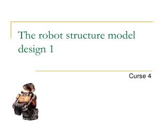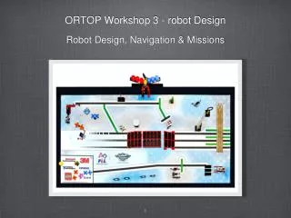
3 AXIS ROBOT MODEL
3 axis Sytrama robot. 3 AXIS ROBOT MODEL. Standard robots components.

3 AXIS ROBOT MODEL
E N D
Presentation Transcript
3 axis Sytrama robot 3 AXIS ROBOT MODEL
Standard robots components The Sytrama robots are assembled using only the highest quality automation components. These units feature quality components from global suppliers such as B&R Automation SMC, etc and offer unparalleled availability for replacement parts should they ever be required • Motors and drives : B&RAutomation • Gearbox : Alpha / Wittenstein • Pneumatics : SMC • Guidings : HWIN/STAR/BoschRexroth • 12Input/12Output standard and free programmable • Standard Euromap 67 ( Euromap 12 / SPI available ) • Software free programmable • Parallelprogramming standard ( F.efor IML applications, controlof down-stream equipment, thisexcludesnecessityofexternal PLC ) • Standard on each robot : onevacuum and onepneumaticcircuit.
Robot 101 GL 101 GL 300-600 ton IMM Payload= 10kg Traverse = 2.500 mm Vertical = 1.400 mm Kick stroke = 800 mm 101 GL equipped with a telescopic vertical arm and single guide When and why does a 101 G need to be offered ? The 101 GL is typically offered in case of low overhead and thus in case the S9 can not be used. By means of the telescopic vertical arm the length of the vertical axis will be lower and more likely to fit in a lower overhead. In case of very restricted overhead there is also the Triple scopic version availble, on request.
Robot Series 201 GL 201 GL 800-1500 ton IMM Payload= 15kg Traverse = 3.000 mm Vertical = 2.000 mm Kick stroke = 1.200 mm This robot is also available, on request, in a 25 Kg payload version which substitutes the 201 GLP
Robot Series 251 G 251 G 1300 -2000 ton IMM Payload= 40 kg Traverse = 3.500 mm Vertical = 2.400 mm Kick stroke = 1.600 mm
Robot Series 301 G 301 G 2000-3500 ton IMM Payload= 50 kg Traverse = 4000 mm Vertical = 2.700 mm Kick stroke = 1.800 mm
Robot Series 401 G 401G 3000-4500 ton IMM Payload= 70 kg Traverse = 4500 mm Vertical = 3.000 mm Kick stroke = 2.000 mm
Reduce your footprint Insufficient space on the side of your moulding machine ? …..Sytrama offers on ALL models the possibility to unload at the rear end of your moulding machine., up to 9.000 mm ( others on special request ) Rear end unloading solution on a 80 TON ( picture ) moulding machine. Sytrama offers this solution in both 2 ( for the Negri Bossi EOS ) and 3 axis configuration ( all axis servo driven )
811G – Side entry 811G 150-550 ton IMM Payload 8 KG Y = 1.600 mm ( movement through belt ) X = 400 mm ( movement through linear motor ) Most common applications : In Mould Labelling, Automation for dispsables , automation for the packaging industry Transversal beam with linear motors . In the picture the magnets are shown….
811G – Side entry – Stacking arm In case the customer requires only a simple pick and place application but has to face fast cycle times the 811 G might be an option. In that case, together with the 811 G , also a stacking arm needs to be offered. On the far right a picture of this servo driven stacking arm is shown. This is the “stand-alone “ version used in pick and place applications. The left immage shows a label feeding system for In-Mold-Labelling applications in which the stacking arm is integrated.
Traverse Robot Axes Names • X = Strip Stroke • Y = Traverse Stroke • Z = Vertical Stroke • A = Rotation • B = Axial Rotation • C = Wrist Flip/Tilting
End of Arm – Quinck changers The picture below represents a series of quick changers we are able to offer with the robot , both robot and gripper side.
SytramaControlPanel Covatta Fausto 12/07/2013
HARDWARE CONFIGURATION • Control and visualization with Mobile Panel Ethernet Desktop (VNC / Total commander / PVI) Laptop (also RS232) CAN E-Stop circuit Cabinet
HARDWARE CONFIGURATION Compact Flash Contains software and data of the entire system USB Port for Backup and Restore user program Pen for Touch Screen
HARDWARE CONFIGURATION • 3 step Enable switch • Adjustable for left and right handers Wall bracket
HARDWARE CONFIGURATION Digital drivers for rotary and linear brushless motors Automatic setting of driver in case of substitution Resolver or Absolute encoder
HARDWARE CONFIGURATION I/O Module expandable and remotable
TEACHING POSITION From the main page select the position to teach: Part pickUp….Deposit…… Sprue cutter…… Pallettizing…….. 1 2 3 4 In few minutes the robot is ready In automatic mode is possible change the position in safety (1mm for typing), timer, counter
VACUUM SWITCH CALIBRATION Setting + + - - + + - -
AIR ENERGY SAVING SYSTEMOptional How much saving each year for one vacuum that work 4 hour each day? 784 € Calculated with SMC software
Control up to 6 axis servo. • Sinchronisation linear axis. • Acceleration and deceleration S ramps a S in order to protect the mechanic.
100 storable programs • 300 program lines • Parallel program • Contemporary execution of various program lines (Max 20)
300 system variables • 100 new system variables customizable for each program (Max 20 characters)
Possibility to rename I/O description • Customized visualisation screen of the variables in order to show to the end user only the ones necessary
Palletising • Extraction Axis with reduction of the torque/couple.
Automatic selection of working cycle through codifcation I.M.M a/o gripper. • Automatic start of the robot cycle through and automatic signal from the I.M.M
Password on various levels • 2 linguages with immediate activation.Various languages storable.
Monitoring of the working conditions : Motor and driver , cycle time total working hours, cycle counts
Remote connection through Ethernet (connection on the cabinet + serial port RS232) Backup programs through USB key