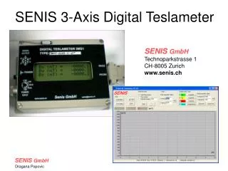
SENIS 3-Axis Digital Teslameter
SENIS 3-Axis Digital Teslameter. SENIS GmbH Technoparkstrasse 1 CH-8005 Zurich www.senis.ch. SENIS. Digital Module. Cable CaH. Connector CoH. Computer. RS 232. Hall Probe. 0.129 T. Voltmeter. Module H. Module E. Output Cable. +/- 12V. Module H. Module E. Power Supply.

SENIS 3-Axis Digital Teslameter
E N D
Presentation Transcript
SENIS 3-Axis Digital Teslameter SENIS GmbH Technoparkstrasse 1 CH-8005 Zurich www.senis.ch SENIS
Digital Module Cable CaH Connector CoH Computer RS 232 Hall Probe 0.129 T Voltmeter Module H Module E Output Cable +/- 12V Module H Module E Power Supply Structure of a Teslameter
CaH X 4.0 Z 1.0 Thin wires 2.0 14.5 50 2.0 < 2 1.1 Z 1.0 14.5 50 mm Y All measures are in millimeters (mm). Module H: Hall Probe 5
Probe with a window • Visible sensitive point • High-accuracy positioning • High-accuracy mapping of magnetic fields
Hall Probe Package C-H3A • Position accuracy of the field sensitive volume: +/- 0.1 mm • Angular accuracy of the axes: +/- 0.5° to the surface.
Thin wires 3 4 0.64 2mm FSV 50 12mm 5 < 2 0.55 mm 2 12 X Z Z Y 3000um Z 150um X 150um 20um 150um 640um Y 550um 150um Type T-H3A Hall Probe 50
Bonding connections Driving part Sensing part Front-end electronics Read-out electronics and buffers 200µm Integrated 3-Axes Hall Probe Chip Dimensions: 4300 µm x 640 µm x 550 µm
Integrated Planar Hall Element • Sensitive to perpendicular • field component B • CMOS Technology: • N-Well • Depletion Layer • Isolation
Integrated Vertical Hall Element • Sensitive to in-plane • field component B • CMOS Technology: • N-Well • Depletion Layer • Isolation
B Bn Bp I α 2 I B sin2α Vp ∞ Planar Hall Effect
ΔR R ΔR R I R R B 2 “Voff” ≡ B ∞ Vp MR long. MR trans. MR Model of the Planar Hall effect
1 2 VH1 = VH2 Reducing Offset: Orthogonal Coupling of Hall Elements 2I0 Vout = VH
Reducing Offset and 1/f Noise « Switched Hall » or « Spinning Current » Technique
Digital Module Computer RS 232 0.129 T Module H Module E Structure of a Teslameter
E-Module: inside Temp.Comp of Sens. Offset Comp. Nonlinearity Comp. Hall probe Sensitivity adjust Temperature conditioning
Analogue Signal Treatment Module H Module E Temp. Comp. of SENSITIVITY VINPOS Cs (T) * X VINNEG Pr_Z SENSITIVITY Adjust. Pr_Y 3D IC Hall Probe X Out_X+ Pr_X Input Amplifier Output Amplifier Pr_T Out_X- 2.5V Cnl (B)*X3 Output Conditioning -2.5V OFFSET Comp. (20 °C) NONLINEARITY Comp. Vpt VINPOS Ct *(T-293K) Dif. Amp. xCt invertor +/- Ct *(T-293K) Vpt(20°C) VINNEG Temp. Comp. of OFFSET
Cancellation of Residual Offset (1) Vx Voff_20 + Ct *(T-293K) Voff_20 Ct *(T-293K) Voff_Out T B = 0 20°C - Ct *(T-293K) (From Temperature Sensor)
Vx + Voff_20 + Ct *(T-293K) B = 0 Vx + Ct *(T-293K) Pr_Z Pr_Y Vx 3D IC Hall Probe X Pr_X Input Amplifier Pr_T 2.5V -2.5V OFFSET Comp. (20 °C) Vpt VINPOS Ct *(T-293K) Dif. Amp. xCt invertor - Ct *(T-293K) Vpt(20°C) VINNEG Temp. Comp. of OFFSET Cancellation of Residual Offset (2): Block Diagram
Analogue Teslameter Specifications • Full scale (nominal) ± 2 T • Output voltages differential • Sensitivity to d.c. magnetic field 5 V/T (0.5mV/G) • Tolerances of sensitivity (B = 1T d.c ) < ± 0.1 % • Temp. coefficient of sensitivity < 100 ppm /°C • Non-linearity of output (B <= 2T) < 0.05 % • Planar Hall effect: Vplan / Vvert (B = 1T) < 0.01% • Long-term instability of sensitivity < 1 % over 10 years • Offset (B = 0T) < ± 1 mV (0.2mT) • Temp. coefficient of offset < (0.02mT/°C) • Temperature out: [T(°C)-(23°C ±0.5°C)]x500mV/°C
Digital Module Computer RS 232 0.129 T Module H Module E Structure of a Teslameter
Digital Module: Functions • 16 bit A/D Conversions of signals from E-Module • Calibration accuracy: up to 0.01% • Digital display of Bx, By, Bz • Fast RS232 interface(115200bps)
Teslameter - User Interface Digital Module Computer Load/Save calibration data Measurement Mode Graph setup Plot Measurement data on screen Serial interface
SENIS GmbH Technoparkstrasse 1 CH-8005 Zurich www.senis.ch