Download
1 / 12
120 likes | 207 Views
Investigation and justification of NSTX Center Stack bellows upgrade design using FEA and EJMA analysis. Examining stress distribution under various load conditions including axial compression, static pressure, and torsional deformation. Comparing EJMA equations with NASTRAN FEA results for validity. Summary of results and implications.

E N D
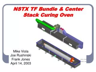
NSTX Center Stack Upgrade Bellows Design Investigation P. Rogoff, 1/19/2011
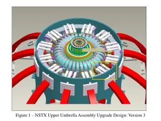
Modulus of Elasticity = 29,000,000. stainless steel (FEA and EJMA) t = variable ( .02, .025, .03 ) in. w = 1.095 in. convolution height q = 1.0 in. convolution pitch Node #49436 – central, RBE2 independent Deformations and loads applied through it. Di = 38.0 inches Do =40.25 inches Fixed : x, y, z, Rx ,Ry, Rz Note: All stresses reported are for cquad4 surface “Z2” . This is the bellows inside surface.
Design justification for the NSTX Update Bellows FEM model simulation: Quad4 NASTRAN element with various convolution thicknesses. For present analyses, .020, .025 and .030 in. Load conditions: 1) 8 mm - Axial compression due to the CS expansion. 2) Static Pressure = 14.5 psi. 3) TORSIONAL deformation = .00315 in. (Applied as pure moment values. which were calculated from P. Titus inputs). 4) Halo Loads Reactions at the bellows ( variable as per bellows thickness as calculated from A. Brooks inputs). Note: Conditions #3 and #4 change, based on the selected material thickness. EJMA equations and related constants were used to test and justify the validity of the FEM simulation using axial deformation and pressure loads: Eq. 4-30, 4-31, 4-32, 4-33 and 4-37. EJMA constants: Cp, Cf and Cd. Figures 4.16, 4.17, 4.18. Figure 4-20 for fatigue life estimates.
Summary of EJMA calculations This data is only valid for Axial deformation and pressure loads
EXPLANATIONS Following can be concluded by examining the above table. * “EJMA” and “MSC/NASTRAN FEA 2010” results compare favorably. * For constant axial deformation of the convoluted bellows (in our case .315 inch), maximum stresses: - decrease with decreasing thickness ( t ), - decrease with increasing convolution height ( w ). ( function of the avowable space) * For constant pressure ( in our case atmospheric , always present) stresses: - increase with decreasing thickness ( t ) - increase slightly with increase of ( w ). * For Halo loads, it is necessary to calculate the bellows Spring Rate in the pure shear mode. Since the spring rate changes with changing thickness, the absorbed amount of the Halo Energy , reacts at the bellows to form the shear deformation. Then this calculated deformation is used, as an enforced load case, in the static FEM simulation. * Toroidal deformation is constant/maximum ( .8e-4 m = .00315 inches) and produce decreasing Torque values with the decrease of ( t )
Maximum Stresses due to individual Load conditions W = 1.095 in. (convolution height), q=1.0 in (convolution pitch)
Questions ? ** What about the usable stress criteria ( Sy or 2/3 Sy) ** How about a possible Pre-load (probably requires some redesign) ** Changing some of the dimensions (Di or Do) ** Changing the Halo loads load path (better restraint)