Download
1 / 7
70 likes | 224 Views
CHI on NSTX Upgrade. C Neumeyer 9/20/11. Topics . Implementation approach 4kV implications Current scenario implications. Implementation approach. Near term efforts should address upgrade features which might prove limiting if not addressed now Coil insulation Structural supports

E N D
CHI on NSTX Upgrade C Neumeyer 9/20/11
Topics • Implementation approach • 4kV implications • Current scenario implications
Implementation approach • Near term efforts should address upgrade features which might prove limiting if not addressed now • Coil insulation • Structural supports • Ceramic insulator etc. • Full implementation later • CHI cap bank • CHI MOVs • Cabling to PF1a • How to organize the effort now? • Piecemeal approach should be avoided to ensure that nothing is overlooked and that full scope is understood • Req’ts document now? • Who should follow up and with what funding source?
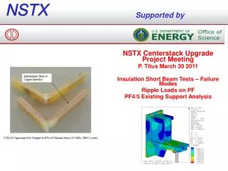
4kV Implications for Upgrade (center stack only) Existing upgrade DP Proposed upgrade DP • Possible plan • Add kapton layers to TF groundwall • Reduce OH operation during CHI from 6kV to 4kV • Implement individual +/- cable runs for inner PF (eliminate 3-wire stackup) • Would preserve safety factor except in TF • Need to investigate # layers glass and kapton and thicknesses and compression to fit existing groundwall build
Current Scenario Implications (3) • I took your CHI max and min forces, for individual coils and combinations and divided them by the max and mins from the design point spreadsheet. • I see the Fr's increased. Coil hoop stresse are small and have enough margin to survive the overage. • The Fz's are all either smaller or close to 1.0 with one noteable exception: the sum of PF1a,bU+PF1a b L • This is the net load on the coils/mandrels supported by the casing bolt circles at the lower flange to the skirt and the skirt to the TF flags. • That net load went from 25161 to 51497 lbs. The skirt and casing flange bolting is addressed in calc 133-03 • The high strength bolts specified for the casing and skirt flange can take the increase, but the TF flag bolting needs to be checked. • Pedestal bolting will have a bit more tension. • We need to understand what loads can occur with the CHI loads.