NSTX Center Stack Upgrade Workshop Requirements and Design Overview
140 likes | 265 Views
This document outlines the requirements and design considerations for the NSTX Center Stack Upgrade. Initiated in April 2008, the project aimed to enhance performance through a detailed analysis of stress and thermal conditions. Key upgrades include an aspect ratio increase, new poloidal field coils, and revised current specifications. A comprehensive spreadsheet methodology has been developed to model system performance, including voltage, flux requirements, and thermal limits. This upgrade targets improved operational capabilities, extending pulse durations while maintaining structural integrity.

NSTX Center Stack Upgrade Workshop Requirements and Design Overview
E N D
Presentation Transcript
NSTX Center Stack UpgradeWorkshopRequirements & Design Point C Neumeyer Jan 22, 2009
Background • Design point spreadsheet studies initiated April ‘08 • Initial approach was aggressive (e.g. 2kV TF, 10kV OH, 2 MG) at A ~ 1.5-1.6 to understand possible envelope • Found that maximum usage of center stack area from simple spreadsheet stress/thermal considerations would allow Ip=3.1MA with 5 sec flat top at B=1.4T • Thought about targeting even higher performance for shorter pulse! • Detailed ANSYS modeling initiated by R Woolley mid-July • Decided to limit to 1kV TF, 8kV OH, 1 MG and round down to Ip=2MA with 5 sec flat top at Bt=1T and investigate design concepts in detail, end of August • Involvement of Mech Eng Div early Oct • PPPL managerial reviews related to mission statement mid-Oct • Small design point iterations followed, no changes since Nov, posted to web at http://www.pppl.gov/~neumeyer/NSTX_CSU/Design_Point.html • Draft GRD circulated mid-Nov
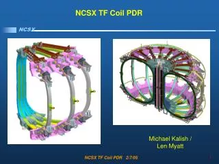
Basic Parameters of Upgrade (1) Aspect ratio* increase to 1.5 from the original value of 1.26 increases the cross sectional area of the center stack by a factor of 3 and makes possible higher levels of performance and pulse duration: * A= R0/a, ratio of plasma major radius R0 to minor radius a
Basic Parameters of Upgrade (3) • New PF inner coils • PF1a,PF1b, Pf1c • Symmetric about midplane • Retain PF outer coils • Increased currents
Basic Parameters of Upgrade (4) • Magnitudes • TF field and current • Bt increases to 1T from 0.6T • R0 increases to 0.934m from 0.854m • Itf increases to 130kA from 71kA • Ip increases to 2MA from 1MA • OH central field increases to 7.3T from 6.9T • PF • - New PF1A/B/C, to replace old PF1a and PF1b, current • - PF2,3,4 currents increase to 24kA from 20kA • - PF5 current increases to 36kA from 20kAT • Approximate force ratios • TF inner leg torque ratio ~ (130/71*7.3/6.9)=1.9 • TF outer leg • in-plane force ratio (130/71)2=3.3 • out-of-plane force ratio ~ (130/71*36/20)=3.3 • - PF axial force ratio ~ (24/20*36/20)=2.2 • - Passive plate & OB divertor force ratio ~ (2/1*36/20)=3.6 • Durations • T_pulse = 5 second plasma flat top • T_rep = 1800 second (30 minute) repetition period • Any combination of T_pulse/T_rep ≤ 5/1800 as long as T_pulse ≤ 5 • TF flat top for full duration when Ip≠0
Basic Desgin Point Assumptions & Limits • Completely replace center stack • New TF same dZ as average turn of original • New OH same dZ as old • Retain existing TF outer legs • TF at flat top for full duration of Ip • Provide OH flux sufficient for Ip ramp in 1st swing • conservative Ip_dot (2MA/sec) • use OH 2nd swing if thermal/stress allows • Retain existing PF outer coils • Coil temperature range 12-100C, assume adiabatic, allow for L/R decay • Simple formulae for TF von Mise stress* and OH hoop stress** (peak) • VM allowable 133 MPA • peak allowable 200MPA • 1kV TF, 8kV/24kA OH, 1 MG • Two TFTR NBI systems imposing MG loads * neglects tension due to force from outer leg ** neglects interaction with PF coils and plasma
Spreadsheet Methology (1) • Includes allowance for details of center stack radial build • Includes allowances for conductor cooling hole, electrical insulation • Adiabatic conductor heating models • Simple formulae for TF inner leg von Mise stress and OH hoop stress • Models not included for TF inner leg torsion, TF outer leg, VV, etc. • Simplified linear power supply models • TF and OH L/R circuit models V = L*I_dot+I*R • MG power and energy models • Plasma loop voltage and flux requirement modeled • OH waveform and flux model accounts for plasma initiation and Ip ramping • XL solver… • finds radius of TF necessary to meet Bt and pulse length requirement • designs OH coil to meet flux requirement of 1st swing, maximizes 2nd swing until thermal
Spreadsheet Methology (2) • “Base” worksheet contains main calculations • Other worksheets provide summary data from “Base” • - results given in both SI and English units • side-by-side comparison of base NSTX to Upgrade • Spreadsheet is protected
Spreadsheet Results (1) • TF bundle requires ~ 70% of center stack radius available to TF and OH • - temperature limited (100oC in case of L/R decay) • - VM stress ~ 30MPA • OH optimizes based on thermal considerations • peak hoop stress at 1st swing 146MPA • temperature limit reached at end of 2nd swing • 1.4 Wb 1st swing flux, bonus 2nd swing flux of 0.5 Wb • Peak MG loading • peak power 289MW/133MVAR/318MVA (47MVA rating) • peak energy 1274MJ (2250MJ available) • start pulse at f>= 77Hz (87.5Hz rating)
Spreadsheet Results (2) Radial Build • Increase in thickness of: • electrical insulation • clearance gaps • CS casing • PFC tiles
Spreadsheet Results (3) TF Coil • Increase in thickness of: • electrical ground insulation • Increase in final temperature of outer legs • Same cooling hole as base (needs assessment) • Allowance for central hole needs to be increased
Spreadsheet Results (3) OH Coil • Increase in thickness of electrical insulation • Similar conductor cross section • Copper mass per winding approx. 2.3x previous, may not be feasible w/o jointing • Same cooling hole as base (needs assessment, cools down in 24 minutes, not 20) • Decreased packing factor • Need to do a trade-off study of 48kA/turn to reduce cooling time, increase packing
Next Steps in Req’ts & Design Point Development • Calculate disruption loads • Determine PFC heat loads • Determine CHI requirements • Issue GRD • Perform OH optimization study • Make other adjustments and refinements as necessary