Rotary Motion
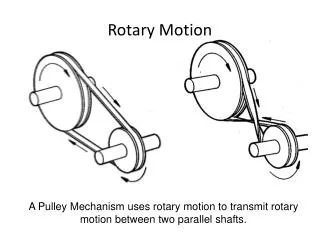
Rotary Motion. A Pulley Mechanism uses rotary motion to transmit rotary motion between two parallel shafts. Mechanisms using Rotary Motion. Pulley mechanisms can be used to increase or decrease rotary velocity. Velocity Ratio. Distance moved by Effort. Velocity Ratio = .

Rotary Motion
E N D
Presentation Transcript
Rotary Motion A Pulley Mechanism uses rotary motion to transmit rotary motion between two parallel shafts.
Pulley mechanisms can be used to increase or decrease rotary velocity
Velocity Ratio Distance moved by Effort • Velocity Ratio = Distance moved by Load Velocity Ratio = Distance moved by the driver pulley Distance moved by the driven pulley Diameter of Driven Pulley • Velocity Ratio = Diameter of Driver Pulley
Velocity Ratio Pulley Shaft Rotary Velocities can be calculated using the following formula rotary velocity of driven pulley x diameter of driven pulley = rotary velocity of driver pulley x diameter of driver pulley rotary velocity of driver pulley x diameter of driver pulley • rotary velocity of driven pulley = diameter of driven pulley
What is the rotary velocity of the driven pulley shaft? rotary velocity of driver pulley x diameter of driver pulley • rotary velocity of driven pulley = diameter of driven pulley 450 x 30 = revs/min 90 = 150 revs/min
Pulleys and Belts Vee pulley and section through a vee pulley and belt A section through a grooved pulley and round belt Stepped cone pulleys provide a range of shaft speeds
Flat belts and pulleys A section through a flat pulley and belt Jockey pulley in use Flat belt in use on a threshing machine
Chains and sprockets Bicycle chain and sprockets Graphical symbols
Velocity Ratio = number of teeth on the driven sprocket number of teeth on the driver sprocket 12 • = 36 • = 1 : 3
Pulleys and Lifting Devices The pulley is a form of Class 1 lever
Pulleys Distance moved by Effort • Velocity Ratio = Distance moved by Load • Velocity Ratio = the number of rope sections that support the load
Two Pulley System Distance moved by Effort • Velocity Ratio = Distance moved by Load 2x • Velocity Ratio = x Velocity Ratio = 2:1
Four Pulley System Distance moved by Effort • Velocity Ratio = Distance moved by Load 4x • Velocity Ratio = x Velocity Ratio = 4:1
Uses Pear shaped cams are used in valve control mechanisms
Springs are used to keep the follower in contact with the cam
Bearings • Bronze • Nylon • PTFE • Air • White metal • Cast Iron • Sintered
Gears Gears are not only used to transmit motion. They are also used to transmit force.
Gears Number of teeth on the driven gear • Mechanical Advantage = Number of teeth on the driver gear Number of teeth on the driven gear • Velocity Ratio = Gear Ratio = Number of teeth on the driver gear
Gears Product of teeth on the driven gears • Gear Ratio = Product of teeth on the driver gears
Basic Gear Geometry http://www.sdp-si.com/D190/PDF/D190T25.PDF
The inclined plane Effort required to pull trolley up slope F = effort E F = 1000 x sin F = 1000 x 0.01 F = 10N E = 10N sin = 1/100 = 0.01 M.A. = 1000/10 = 100 Follow link to see effects of steeper incline: http://lectureonline.cl.msu.edu/~mmp/applist/si/plane.htm