DAQ Overview
DAQ Overview. Jean-Sebastien Graulich, Geneva. Terminology Requirements Front End Electronics Trigger System DAQ Hardware and Software Event Building and Data Flow Interfaces: Monitoring, Controls, G4MICE, and Configuration DB Project Plan: Human resources and Time Line.


DAQ Overview
E N D
Presentation Transcript
DAQ Overview Jean-Sebastien Graulich, Geneva • Terminology • Requirements • Front End Electronics • Trigger System • DAQ Hardware and Software • Event Building and Data Flow • Interfaces: Monitoring, Controls, G4MICE, and Configuration DB • Project Plan: Human resources and Time Line Jean-Sebastien Graulich
DAQ Terminology • ISIS / MICE / DATE Jargon • Isis Cycle: • The injection and acceleration cycle of ISIS. It is 20 ms long (50 Hz). • Machine Start or MS: • This is the pulse used for the ISIS synchronization • Spill or Spill-Gate: • The time window during which the MICE Target is crossing the ISIS beam. The Spill cycle is driven by the cycle of the MICE target • Burst: • The ~100 ns time window during which muons can be expected in the MICE detectors. It corresponds to the time it takes for a proton bunch in ISIS to cross through the MICE target • DAQ-Trigger: • Signal triggering the readout of the FE-electronics modules of the MICE detectors. By definition, one DAQ-Trigger corresponds to one DAQ-Event • Particle-Trigger: • Signal generated when the desired Trigger Condition is met. It is distributed to the sub-detectors Front End Electronics and initiates the digitization of the data therein.By definition, a Particle-Trigger corresponds to one Particle-Event Jean-Sebastien Graulich
Requirements • See the full list of system requirement in MICE Note 222. • The main requirement is on the rate: 3.2.1 The DAQ system should allow acquiring data for up to 600 Particles in a 1 ms spill repeating at 1 Hz. • Important consequences Detector data Readout must be performed at the end of the spill Data has to be buffered in the FEE This is because the readout of 1 particle event takes several 100 µs… Jean-Sebastien Graulich
Requirements (2) • Digitization dead time 4.3.4 The DAQ dead time after a Particle Trigger should not exceed one burst after the one that generated it. • Average Time between 2 muons is 1.7 µs • Conversion time for conventional ADC > ~3 µs • Critical for EMCal and TOF • Solution: Flash ADC after Signal stretching Even if the event buffer was large enough, conventional ADC can not collect 600 muons/ms Jean-Sebastien Graulich
Charge Measurement in MICE (except Tracker) 100 MHz Flash ADCs (CAEN 1724) • Advantages • No Splitter, no delay cable, no discri, no TDC ! • Cabling very easy • Need custom made shaper • Strong impact on data size Shaper Vthr tthr >30 ns rise time 2 ns rise time By fitting the rising edge, time resolution is much better than the 10 ns of the sampling rate (~1 ns obtained). Jean-Sebastien Graulich
Requirements (3) • Event Size • DAQ Event Size is quite large because it corresponds to 600 muons 3.2.3 The DAQ system should be able to deal with DAQ event size up to 60 MB (up to 10 MB per sub-event) • Means ~ 60 MB/s data transfer rate (readout between spills) Jean-Sebastien Graulich
Requirements (4) • Stability and Reliability • Flexibility • Partitioning • Following MICE Installation plan • Allow calibration events between spills • AND maintainable by a single person… Jean-Sebastien Graulich
Front End Electronics • TOF • KL • CKOV • Tracker • EMR • Target Position and Beam Loss Jean-Sebastien Graulich
TOF FEE • Sensor: PMT (Hamamatsu R4998) • Signal transmission: Single ended, 50 Ohm, coax cable (RG213) • Number of Channels • 40 (TOF0) + 28 (TOF1) + 40 (TOF2) = 108 ch • Main Constrain • Time Resolution • -> Time-walk correction • TDC • CAEN V1290, 32 ch • Large Event Buffer • ECL input • Discriminator • Lecroy 4415 • 16 Channels • ECL output • Twisted Pair Input (110 Ohm) • Need Signal splitting • for charge measurement Jean-Sebastien Graulich
KL FEE • Sensor: PMT (Hamamatsu R1355) • Signal transmission: Differential, 120 Ohm, Twisted pair cable • Number of Channels • 42 ch • Main Constrain • Charge measurement • Time ~ 1 ns • Flash ADC (WFD) • CAEN V1724 • 100 MS/s, 14 bits • Best commercial deal • Single Ended, 50 OhmInput Jean-Sebastien Graulich
Shaper development • Splitter designed in Geneva (P. Bene) • Passive splitter, shielded, impedance matched (minimal signal loss) • 16 x Lemo, 50 Ohm Input • 2 twisted pair outputs, 34 contacts connectors, 110 Ohm to Discriminator 120 Ohm to Shaper • Shaper designed in Sofia (I. Rusinov) • 120 Ohm Twisted Pair Input, 34 contacts connectors • 16 Lemo, 50 Ohm, single-ended outputs to fADC • Single-Ended or Differential mode jumper selectable BNC Cable 50 Ohm DISCRI TDC TOF PMT Splitter Trigger Logic Shaper SE Mode fADC P-Trg Signal Twisted pair Cable KL PMT ShaperDiff Mode fADC Jean-Sebastien Graulich
Shaper and Splitter Jean-Sebastien Graulich
Shaper Output - Signal shape well understood - Time resolution better than 1 ns Need for better tuning of baseline restorer Used for individual baseline evaluation Time (sample) F(t) = offset – norm(t0/(t0-t))[(e-(t-t0)/t-e-(t-t0)/t0) + (t-t0)/t e-(t-t0)/t ] Jean-Sebastien Graulich
CKOV FEE • Sensor: PMT (8”) • Signal transmission: Single ended, 50 Ohm, coax cable (RG58) • Number of Channels • 4 + 4 = 8 ch • Main Constrain • Rate (no segmentation) • Small charge • Flash ADC (WFD) • CAEN V1731 • 500 MS/s, 8 bits • Single Ended, 50 OhmInput • No Shaper ! Jean-Sebastien Graulich
Tracker FEE • Custom Made Digital Data Buffer • VLSB = VME LVDS CERDES Buffer • MICE defined Data format • Measure Both discriminated time and Zero suppressed Charge • 4096 + 4096 = 8198 channels 4 VLSB Boards in VME Crate = Data Buffer 1 Cryo-Cooler = ½ Tracker Read out PC In Control Room Fibers from VLPCs Optical Fiber 4 AFE2-t Boards Digital Signal MIL1553(Control) MICE HALL Jean-Sebastien Graulich
EMR FEE • Still in prototyping phase • 50 layers x 59 bars = 2950 channels • Digital information only • only -> 2950 bits (100 words = 400 bytes) • In custom made VME buffer (similar to tracker) • Charge measurement per layer only • 50 fADC channel • Direct connection, similar to CKOV Jean-Sebastien Graulich
Target Monitoring FEE • The Target system records • Target dip trajectory • ISIS Beam loss monitors analog signals • Duplicate data flow • CAM • DAQ • Max 8 channels • Read out once per spill • Nuclear Instrument PCI I/O card PCi6254 • in target PC • Marginal in term of data size Jean-Sebastien Graulich
Data Size • TOF TDC: Maximum 108 hits, 4 bytes/hit • 432 bytes/pt • TOF fADC: 60 samples per channel • 13 kBytes/pt • KL fADC: 60 samples per channel • 6 kBytes/pt • CKOV fADC 300 samples per channel, 1 byte/sample • 2.4 kB/pt • Tracker: (w/o zero suppression) 5536 bytes per tracker/pt • 10.8 kB/pt • TOTAL w/o EMR: • ~33 kB/pt • 16.5 MB/Spill • Maximum 16.5 MB/s • Electron Muon Ranger (Coming up after spring 2010) • Digital: 0.4 kB/pt or 2 kB/pt if TDC information • fADC: 300 samples/ch, 1 byte/sample: 15kB/pt • TOTAL for EMR: 21 kB/pt -> 10.5 MB/Spill -> 10.5 MB/s • TOTAL at completion • ~ 30 MB/s Jean-Sebastien Graulich
Trigger System • Particle Trigger • Timing • Logic • DAQ Trigger • Spill Gate Jean-Sebastien Graulich
Particle Trigger • Triggers the digitization of the signals arriving at the Front End Electronics • Should arrive a few ms around the signal • Distributed to all FEE boards • We expect about 500 Particle triggers for 1 DAQ trigger • The timing of the trigger should be given by the burst • Delay TOF0, TOF1 TOF2 such that they arrive approximately at the same time in the trigger logic • Make the TOF logic pulses ~200 ns long • Make the Burst Gate narrow and Delay it such that it arrives more than 100 ns after the TOF signals • All single raw time distribution will be ~ 100 ns wide • Problem for beam commissioning ! • Protons have very different timing • Will use TOF0 timing until stable muon running is established Jean-Sebastien Graulich
Particle Trigger timing Burst Gate 200 ns TOF0 TOF1 TOF0 TOF1 Burst Gate GVA1 hit Burst Gate (made narrow) Jean-Sebastien Graulich
TOF0 Logic TOF0 signal is the OR over all the slabs of the AND of the two pmts of each slab Because of hardware constraints, Wealsodefine TOF0_H: OR over 8 central H slabs TOF0_V: OR over 8 central V slabs TOF0_EXT: OR over the 4 frame slabs • TOF0 has 40 channels • 10 horizontal slabs • 10 vertical slabs • 2 PMts per slab Jean-Sebastien Graulich
TOF0 Logicimplementation TOF1 will be included in the trigger in a similar way Jean-Sebastien Graulich
Trigger Electronics Interfacew/Target & Spill Gate DAQ Trigger distribution KL Scalars and particle trigger NIM Logic Shapers GVA Discri, KL cosmics trg TOF & CKOV TOF discriminators and trigger CAMAC Logic Crate Layout Jean-Sebastien Graulich
MICE Systems synchronization MICE Ready DAQ Ready Target Ready RF Ready Spill Request 20 ms Extraction Gated Machine Start Validated Machine Start Target Delay Target Trigger Protons on target RF Delay RF Trigger RF Power DT Delay DT Gate DAQ Trigger
DAQ Trigger Four types of DAQ triggers - PHYSICS - CALIBRATION - Start of Spill - End of Spill Event Type istagged in the data header Used to impose a well-definedsequence of events and online check of synchronisation Jean-Sebastien Graulich
DAQ trigger distribution VMS Fixed delay SOS Trigger Fan out to LDCs Target Trg Software Check: No overlap with SOS busy (otherwise stop with error) Fixed delay ~ few ms Particle Triggers Fixed width ~ 1 ms Physics Event DAQ Trigger Fan out to LDCs Depends on Data Size ~ 1 s EOS Trigger Fan out to LDCs DAQ Idle = DAQ Ready
CAEN V977 Channels 0-7 configured as Flip-Flop, reset by software
DAQ Spill Gate Detailed documentation of the procedure to adjust the DAQ Spill Gate is available Machine start after delay in the target system Spill Gate is always aligned to extraction Jean-Sebastien Graulich
DAQ Spill Gate Sync Hits in GVA1 Machine Start DAQ Gate ~ 3.5ms Jean-Sebastien Graulich
DAQ Hardware and Software • Hardware overview • Software Framework • Event Building • Data flow Jean-Sebastien Graulich
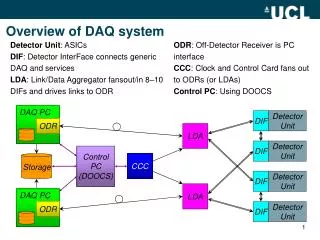
D-DAQ Hardware Overview Jean-Sebastien Graulich
Software Framework • MICE has decided to use the ALICE DAQ software framework • The ALICE DAQ software framework, DATE, will provide us with the necessary EventBuilder tool: Subevents collected by different processors have to be synchronized and put together before storage • DATE has much more functionalities than what MICE needs • Previous Experience (from HARP) Experiment could be used • Agreement with ALICE collaboration included 6 months hands on training with real contribution to the software (2006) • Currently using DATE version 6.05 (20/06/2007) • Historical reasons • Upgrade in July and then froze it until the end of the experiment Jean-Sebastien Graulich
DATE Vocabulary • LDC : Local Data Concentrator • The PC connected to the VME crate via the PC-VME Interface • GDC : Global Data Collector • Event Builder • Event • DATE Event = DAQ Event !!! It contains data for several Particle Events (~500) • Event Type • Tag attached to the event depending on which trigger receiver‘s input has been used Jean-Sebastien Graulich
DATE Readout Process • Two processes running in each LDC • The readout process waits for a trigger, reads out the front-end electronics, and fills a FIFO buffer with the sub-event data • The recorder process off-loads the FIFO and sends the sub-event data to one (or several) GDC over the network • Each LDC contains a set of Equipments • Equipment =~ 1 Vme board (in MICE) • Each equipment has its own set of routines for its initialization and readout. • Adding an equipment is done without recompiling all DATE • Equipment configuration data is saved in MYSQL database (but not archived) Jean-Sebastien Graulich
DATE Readout Algorithm • General algorithm for equipment readout: 5 user routines have to be implemented (XXX is the name of the equipment) • ArmHwXXX • Executed at the beginning of the Run • Allows initialization of the board • AsynchReadXXX • Executed constantly even when there is no trigger • Don’t use ! • EventArrivedXXX • Used only if the equipment needs to trigger the readout ( Trigger Receiver) • ReadEventXXX • That is the readout itself • DisArmHwXXX • Executed at the end of the Run Jean-Sebastien Graulich
Readout Code • Available and tested for • TDC V1290A (TOF) • FADC V1724 (TOF and KL) • FADC V1731 (CKOV and EMR) • Scaler V830 • Trigger Receiver I/O V977 • NI I/O PCi 6254 (Target) • VLSB (Tracker) • Trailer (special equipment handling the release of the busy) • Todo • EMR Front End Board Jean-Sebastien Graulich
DATE Data Format • The data sent by the equipment is just wrapped with a LDC header (+ a GDC header if used) • The data format in the payload is defined by the manufacturer of the equipment ! (we will stick to 32 bits words) • DATE Header format defined in a header file event.h This file contains all the information the offline codes needs to know about DATE Data from the equipment -> Jean-Sebastien Graulich
Interfaces • Online Monitoring • Reconstruction • Controls • Configuration Data Base Jean-Sebastien Graulich
Online Monitoring • Interface is based on DATE monitoring facility • A simplified version independent from DATE (running only from files) exists • Online monitoring process produces histograms and makes then available on demand on a ROOT socket • Socket handling implemented has a thread to avoid clashes with DATE monitoring semaphore system • Online Monitoring GUI is just a ROOT macro allowing the user to request histograms • See Linda’s talk Jean-Sebastien Graulich
Reconstruction • Unpacking has to take into account the DATE format • Common library for online monitoring and Reconstruction • Dependency limited to the event.h file • All implemented in C++ Jean-Sebastien Graulich
Control And Monitoring • Two ways Interface • CAM should know the DATE status • A summary of CAM data should be inserted in the online data stream • The run should stop automatically when the CAM goes in severe alarm state • An EPICS Client uses the DIM layer of DATE to make the status available • A special DATE equipment will be implemented to readout some CAM data identified as relevant for Offline Analysis • Currently under development • The same equipment will stop the run if a dedicated CAM variable is set • More details in James’ and Pierrick’s talks Jean-Sebastien Graulich
Configuration Database • The Equipment Parameters (configuration of the VME boards) will be stored in the configuration database • A run configuration file (in xml format) will be saved in the CDB each time a run is started • The CAM monitors DAQ status • When the run starts, the CAM calls an API function saving the configuration file automatically • More details in David’s talk Jean-Sebastien Graulich
Project Plan • Organization and Resources • Time Line Jean-Sebastien Graulich
Organization • Online Group • Responsibilities • Detector DAQ : J.S Graulich (80%) (Group Leader) • Control and Monitoring: J. Leaver (50%) P. Hanlet (20%) • Online Reconstruction: L. Coney (20%) • MLCR Manager: C. MacWaters (20%) • Other Contributors • Vassil Verguilov (DAQ) • David Forrest (Config DB) • Henry Nebrensky (GRID – Data Flow) • Mike Courthold (Network Supervisor) Jean-Sebastien Graulich
Time Line • Project started from scratch in July 2005 • First data taken acquired in March 2008 • The DAQ is running stable with some limitations • Trigger selection by hardware • Limit on DAQ Event Size is currently 30 MB • July 2009: • Integration of Tracker in DAQ • Include CAM Data in Online data stream (at the Spill level) • Current Priority: • Problem with DAQ trigger distribution system • Cause Event building desync • Need to include that in the Online Monitoring • Include EMR • Include RF System ! Jean-Sebastien Graulich
The Cat only grinned when it saw Alice. It looked good- natured, she thought: still it had VERY long claws and a great many teeth, so she felt that it ought to be treated with respect. `Cheshire Puss,' she began, rather timidly, as she did not at all know whether it would like the name: however, it only grinned a little wider. `Come, it's pleased so far,' thought Alice, and she went on. `Would you tell me, please, which way I ought to go from here?' `That depends a good deal on where you want to get to,' said the Cat. `I don't much care where--' said Alice. `Then it doesn't matter which way you go,' said the Cat. `--so long as I get SOMEWHERE,' Alice added as an explanation. `Oh, you're sure to do that,' said the Cat, `if you only walk long enough. ' Alice felt that this could not be denied, so she tried another question. `What sort of people live about here?' `In THAT direction,‘ the Cat said, waving its right paw round, `lives a Hatter: and in THAT direction,' waving the other paw, `lives a March Hare. Visit either you like: they're both mad.' `But I don't want to go among mad people,' Alice remarked. `Oh, you can't help that,' said the Cat: `we're all mad here. I'm mad. You're mad.‘ `How do you know I'm mad?' said Alice. `You must be,' said the Cat, `or you wouldn't have come here.' Jean-Sebastien Graulich