Download
1 / 11
110 likes | 131 Views
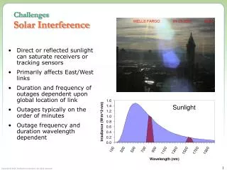
Challenges Solar Interference. Direct or reflected sunlight can saturate receivers or tracking sensors Primarily affects East/West links Duration and frequency of outages dependent upon global location of link Outages typically on the order of minutes

E N D
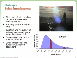
ChallengesSolar Interference • Direct or reflected sunlight can saturate receivers or tracking sensors • Primarily affects East/West links • Duration and frequency of outages dependent upon global location of link • Outages typically on the order of minutes • Outage frequency and duration wavelength dependent Sunlight
Transceiver DesignBasic Design Transceiver Trades • Design Constraints • Price Point • Range and Availability • Data Rate • Major Technical Choices • Wavelength • Wide Divergence Vs. Automatic Pointing and Tracking • Single-Transmitter Vs. Multi-Transmitter • Direct Coupling Vs. Fiber Coupling
FSO (30-400 THz) MMDS,U-NII, ISM Visible Light Gamma Ray MillimeterWave Ultra-Violet Infrared Microwave Radio ~400-700nm 300 GHz 30 GHz 10 GHz Transceiver DesignChoosing a Wavelength X-Ray • FSO wavelengths selected for low atmospheric molecular absorption
Laser Pointer – Narrow Divergence Flashlight – Wide Divergence Transceiver DesignDivergence Vs. Pointing and Tracking • Wide Divergence • Easier to keep on target • Low cost • Narrow Divergence • Stronger signal at the receiver • Longer range • Higher availability • Requires automatic pointing and tracking for building motion • Security Considerations • Wider beams are easier to intercept
Transceiver DesignField of View (FOV) Field of View Cone • FOV is the receiver’s equivalent of divergence • If light doesn’t originate within the defined cone, the receiver won’t see it (e.g., Laser 2) • Smaller FOV means less noise entering system • Small FOV makes interference highly unlikely • High data rate detectors typically have small FOVs • FOV also drives the need for pointing and tracking Laser 1 Receiver Laser 2
Laser Transceiver DesignAutomatic Pointing & Tracking Systems • Compensates for base motion • Adjusts to maintain alignment of receiver and transmitter • Essential for narrow divergence/FOV systems Receiving Optics Steering Mirror GimbalMotors
Transceiver DesignSingle Transmitter Vs. Multi-Transmitter Spot Size = X Spot Size = X+Y Distance Between Centers = Y
Transceiver DesignSingle Transmitter Vs. Multi-Transmitter • At long range, the multiple beams merge into one • No inherent power or alignment advantages • Does offer significant advantages for overcoming the effects of scintillation • Typically not important for high availability fog limited installations
Transceiver DesignDirect Coupling Vs. Fiber Coupling • Direct Coupling • Light is focused directly onto the detector • Allows for a large FOV • Electronics closely coupled to optics • Low cost Detector • Fiber Coupling • Light is focused onto the end of a fiber • Eventually the fiber connects to a detector • May be after several FSO links • Fiber requires a small FOV • Pointing and tracking required • Not required for data rates <2.5 Gbps • The Ultimate vision of FSO – Fiber through the air Fiber