Addressing Challenges in Free Space Optics Transceiver Design for Optimal Performance
Free Space Optics (FSO) systems face significant challenges due to solar interference, particularly affecting East/West links, causing temporary outages. These interruptions depend on global geographic locations and can last minutes, impacting the design of transceivers. Key considerations involve overcoming obstructions, selecting wavelengths for minimal atmospheric absorption, and deciding between single or multi-transmitter setups. The design must balance costs, range, and data rates while ensuring alignment through advanced pointing and tracking systems, and addressing security and FOV limitations.

Addressing Challenges in Free Space Optics Transceiver Design for Optimal Performance
E N D
Presentation Transcript
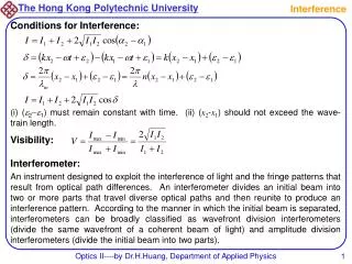
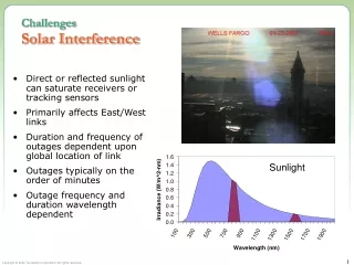
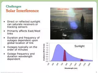
ChallengesSolar Interference • Direct or reflected sunlight can saturate receivers or tracking sensors • Primarily affects East/West links • Duration and frequency of outages dependent upon global location of link • Outages typically on the order of minutes • Outage frequency and duration wavelength dependent Sunlight
Transceiver DesignBasic Design Transceiver Trades • Design Constraints • Price Point • Range and Availability • Data Rate • Major Technical Choices • Wavelength • Wide Divergence Vs. Automatic Pointing and Tracking • Single-Transmitter Vs. Multi-Transmitter • Direct Coupling Vs. Fiber Coupling
FSO (30-400 THz) MMDS,U-NII, ISM Visible Light Gamma Ray MillimeterWave Ultra-Violet Infrared Microwave Radio ~400-700nm 300 GHz 30 GHz 10 GHz Transceiver DesignChoosing a Wavelength X-Ray • FSO wavelengths selected for low atmospheric molecular absorption
Laser Pointer – Narrow Divergence Flashlight – Wide Divergence Transceiver DesignDivergence Vs. Pointing and Tracking • Wide Divergence • Easier to keep on target • Low cost • Narrow Divergence • Stronger signal at the receiver • Longer range • Higher availability • Requires automatic pointing and tracking for building motion • Security Considerations • Wider beams are easier to intercept
Transceiver DesignField of View (FOV) Field of View Cone • FOV is the receiver’s equivalent of divergence • If light doesn’t originate within the defined cone, the receiver won’t see it (e.g., Laser 2) • Smaller FOV means less noise entering system • Small FOV makes interference highly unlikely • High data rate detectors typically have small FOVs • FOV also drives the need for pointing and tracking Laser 1 Receiver Laser 2
Laser Transceiver DesignAutomatic Pointing & Tracking Systems • Compensates for base motion • Adjusts to maintain alignment of receiver and transmitter • Essential for narrow divergence/FOV systems Receiving Optics Steering Mirror GimbalMotors
Transceiver DesignSingle Transmitter Vs. Multi-Transmitter Spot Size = X Spot Size = X+Y Distance Between Centers = Y
Transceiver DesignSingle Transmitter Vs. Multi-Transmitter • At long range, the multiple beams merge into one • No inherent power or alignment advantages • Does offer significant advantages for overcoming the effects of scintillation • Typically not important for high availability fog limited installations
Transceiver DesignDirect Coupling Vs. Fiber Coupling • Direct Coupling • Light is focused directly onto the detector • Allows for a large FOV • Electronics closely coupled to optics • Low cost Detector • Fiber Coupling • Light is focused onto the end of a fiber • Eventually the fiber connects to a detector • May be after several FSO links • Fiber requires a small FOV • Pointing and tracking required • Not required for data rates <2.5 Gbps • The Ultimate vision of FSO – Fiber through the air Fiber