DC Choppers
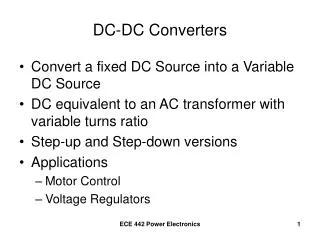
DC Choppers. 1. Prof. T.K. Anantha Kumar, E&E Dept., MSRIT. Introduction. Chopper is a static device. A variable dc voltage is obtained from a constant dc voltage source. Also known as dc-to-dc converter. Widely used for motor control. Also used in regenerative braking.


DC Choppers
E N D
Presentation Transcript
DC Choppers 1 Prof. T.K. Anantha Kumar, E&E Dept., MSRIT
Introduction • Chopper is a static device. • A variable dc voltage is obtained from a constant dc voltage source. • Also known as dc-to-dc converter. • Widely used for motor control. • Also used in regenerative braking. • Thyristor converter offers greater efficiency, faster response, lower maintenance, smaller size and smooth control. 2 Prof. T.K. Anantha Kumar, E&E Dept., MSRIT
Choppers are of Two Types • Step-down choppers. • Step-up choppers. • In step down chopper output voltage is less than input voltage. • In step up chopper output voltage is more than input voltage. 3 Prof. T.K. Anantha Kumar, E&E Dept., MSRIT
Principle Of Step-down Chopper 4 Prof. T.K. Anantha Kumar, E&E Dept., MSRIT
A step-down chopper with resistive load. • The thyristor in the circuit acts as a switch. • When thyristor is ON, supply voltage appears across the load • When thyristor is OFF, the voltage across the load will be zero. 5 Prof. T.K. Anantha Kumar, E&E Dept., MSRIT
6 Prof. T.K. Anantha Kumar, E&E Dept., MSRIT
7 Prof. T.K. Anantha Kumar, E&E Dept., MSRIT
8 Prof. T.K. Anantha Kumar, E&E Dept., MSRIT
9 Prof. T.K. Anantha Kumar, E&E Dept., MSRIT
10 Prof. T.K. Anantha Kumar, E&E Dept., MSRIT
11 Prof. T.K. Anantha Kumar, E&E Dept., MSRIT
12 Prof. T.K. Anantha Kumar, E&E Dept., MSRIT
Methods Of Control • The output dc voltage can be varied by the following methods. • Pulse width modulation control or constant frequency operation. • Variable frequency control. 13 Prof. T.K. Anantha Kumar, E&E Dept., MSRIT
Pulse Width Modulation • tON is varied keeping chopping frequency ‘f’ & chopping period ‘T’ constant. • Output voltage is varied by varying the ON time tON 14 Prof. T.K. Anantha Kumar, E&E Dept., MSRIT
15 Prof. T.K. Anantha Kumar, E&E Dept., MSRIT
Variable Frequency Control • Chopping frequency ‘f’ is varied keeping either tONor tOFF constant. • To obtain full output voltage range, frequency has to be varied over a wide range. • This method produces harmonics in the output and for large tOFFload current may become discontinuous 16 Prof. T.K. Anantha Kumar, E&E Dept., MSRIT
17 Prof. T.K. Anantha Kumar, E&E Dept., MSRIT
Step-down ChopperWith R-L Load 18 Prof. T.K. Anantha Kumar, E&E Dept., MSRIT
When chopper is ON, supply is connected across load. • Current flows from supply to load. • When chopper is OFF, load current continues to flow in the same direction through FWD due to energy stored in inductor ‘L’. 19 Prof. T.K. Anantha Kumar, E&E Dept., MSRIT
Load current can be continuous or discontinuous depending on the values of ‘L’ and duty cycle ‘d’ • For a continuous current operation, load current varies between two limits Imaxand Imin • When current becomes equal to Imaxthe chopper is turned-off and it is turned-on when current reduces to Imin. 20 Prof. T.K. Anantha Kumar, E&E Dept., MSRIT
21 Prof. T.K. Anantha Kumar, E&E Dept., MSRIT
Expressions For Load CurrentiO For Continuous Current Operation When Chopper Is ON (0 t tON) 22 Prof. T.K. Anantha Kumar, E&E Dept., MSRIT
23 Prof. T.K. Anantha Kumar, E&E Dept., MSRIT
24 Prof. T.K. Anantha Kumar, E&E Dept., MSRIT
25 Prof. T.K. Anantha Kumar, E&E Dept., MSRIT
When Chopper is OFF 26 Prof. T.K. Anantha Kumar, E&E Dept., MSRIT
27 Prof. T.K. Anantha Kumar, E&E Dept., MSRIT
28 Prof. T.K. Anantha Kumar, E&E Dept., MSRIT
29 Prof. T.K. Anantha Kumar, E&E Dept., MSRIT
30 Prof. T.K. Anantha Kumar, E&E Dept., MSRIT
31 Prof. T.K. Anantha Kumar, E&E Dept., MSRIT
32 Prof. T.K. Anantha Kumar, E&E Dept., MSRIT
33 Prof. T.K. Anantha Kumar, E&E Dept., MSRIT
34 Prof. T.K. Anantha Kumar, E&E Dept., MSRIT
35 Prof. T.K. Anantha Kumar, E&E Dept., MSRIT
36 Prof. T.K. Anantha Kumar, E&E Dept., MSRIT
37 Prof. T.K. Anantha Kumar, E&E Dept., MSRIT
38 Prof. T.K. Anantha Kumar, E&E Dept., MSRIT
39 Prof. T.K. Anantha Kumar, E&E Dept., MSRIT
Principle Of Step-up Chopper 40 Prof. T.K. Anantha Kumar, E&E Dept., MSRIT
Step-up chopper is used to obtain a load voltage higher than the input voltage V. • The values of L and C are chosen depending upon the requirement of output voltage and current. • When the chopper is ON, the inductor L is connected across the supply. • The inductor current ‘I’ rises and the inductor stores energy during the ON time of the chopper, tON. 41 Prof. T.K. Anantha Kumar, E&E Dept., MSRIT
When the chopper is off, the inductor current I is forced to flow through the diode D and load for a period, tOFF. • The current tends to decrease resulting in reversing the polarity of induced EMF in L. • Therefore voltage across load is given by 42 Prof. T.K. Anantha Kumar, E&E Dept., MSRIT
A large capacitor ‘C’ connected across the load, will provide a continuous output voltage . • Diode D prevents any current flow from capacitor to the source. • Step up choppers are used for regenerative braking of dc motors. 43 Prof. T.K. Anantha Kumar, E&E Dept., MSRIT
Expression For Output Voltage 44 Prof. T.K. Anantha Kumar, E&E Dept., MSRIT
45 Prof. T.K. Anantha Kumar, E&E Dept., MSRIT
46 Prof. T.K. Anantha Kumar, E&E Dept., MSRIT
47 Prof. T.K. Anantha Kumar, E&E Dept., MSRIT
48 Prof. T.K. Anantha Kumar, E&E Dept., MSRIT
Performance Parameters • The thyristor requires a certain minimum time to turn ON and turn OFF. • Duty cycle d can be varied only between a min. & max. value, limiting the min. and max. value of the output voltage. • Ripple in the load current depends inversely on the chopping frequency, f. • To reduce the load ripple current, frequency should be as high as possible. 49 Prof. T.K. Anantha Kumar, E&E Dept., MSRIT
Problem • A Chopper circuit is operating on TRC at a frequency of 2 kHz on a 460 V supply. If the load voltage is 350 volts, calculate the conduction period of the thyristor in each cycle. 50 Prof. T.K. Anantha Kumar, E&E Dept., MSRIT