DC-DC Converters
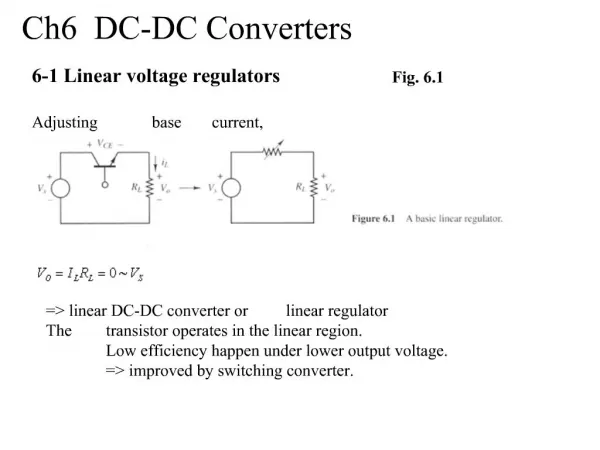
DC-DC Converters. Convert a fixed DC Source into a Variable DC Source DC equivalent to an AC transformer with variable turns ratio Step-up and Step-down versions Applications Motor Control Voltage Regulators. Step-down Operation. Switch SW is known as a “Chopper” Use BJT, MOSFET, or IGBT


DC-DC Converters
E N D
Presentation Transcript
DC-DC Converters • Convert a fixed DC Source into a Variable DC Source • DC equivalent to an AC transformer with variable turns ratio • Step-up and Step-down versions • Applications • Motor Control • Voltage Regulators ECE 442 Power Electronics
Step-down Operation • Switch SW is known as a “Chopper” • Use BJT, MOSFET, or IGBT • Close for time t1 • VS appears across R • Open for time t2 • Voltage across R = 0 • Repeat • Period T = t1 + t2 ECE 442 Power Electronics
Waveforms for the Step-Down Converter ECE 442 Power Electronics
Average Value of the Output Voltage ECE 442 Power Electronics
Average Value of the Load Current ECE 442 Power Electronics
rms Value of the output voltage ECE 442 Power Electronics
If the converter is “lossless”, Pin = Pout ECE 442 Power Electronics
Effective Input Resistance seen by VS ECE 442 Power Electronics
Modes of Operation • Constant – frequency operation • Period T held constant, t1 varied • Width of the pulse changes • “Pulse-width modulation”, PWM • Variable -- frequency operation • Change the chopping frequency (period T) • Either t1 or t2 is kept constant • “Frequency modulation” ECE 442 Power Electronics
Generation of Duty Cycle • Compare a dc reference signal with a saw-tooth carrier signal DC Reference Signal Carrier Signal ECE 442 Power Electronics
kT ECE 442 Power Electronics
To generate the gating signal • Generate the triangular waveform of period T, vr, and the dc carrier signal, vcr • Compare to generate the difference vc - vcr • Apply to a “hard limiter” to “square off” ECE 442 Power Electronics
Step-Down Converter with RL Load ECE 442 Power Electronics
Mode 1: Switch Closed ECE 442 Power Electronics
Mode 2: Switch Open ECE 442 Power Electronics
Current for “Continuous” Mode ECE 442 Power Electronics
For Continuous Current ECE 442 Power Electronics
Define the load emf ratio ECE 442 Power Electronics
Example 5.2 ECE 442 Power Electronics
SPICE Results ECE 442 Power Electronics