Download
1 / 67
680 likes | 713 Views
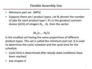
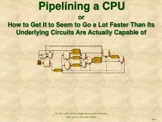
CPU Pipelining an assembly line. Today’s CPUs are pipelined (4.5 – 4.8 4 th ed). Pipelining Overview. Basic idea :: assembly line, visit El Abd downtown Pipelined datapath Data hazards: pipelining problems Solutions to pipelining problems Controlling the pipeline

E N D
CPU Pipeliningan assembly line Today’s CPUs are pipelined (4.5 – 4.8 4th ed)
Pipelining Overview • Basic idea :: assembly line, visit El Abd downtown • Pipelined datapath • Data hazards: pipelining problems • Solutions to pipelining problems • Controlling the pipeline • Advanced pipelining – Dynamic branch • Advanced pipelining – Superscalar Benz 2015 C-class • https://www.youtube.com/watch?v=tb_1TrpUrmQ
1966 Mustang Assembly Line, Michigan Ford Mustang 19666 assembly line, Michigan
MIPS Pipeline:: 5 steps 5 stages RTL Notation: register transfer level IR <= mem[PC]; PC <= PC + 4 • IF: instruction fetch • ID: inst. decode and register fetch • EX: execute / effective addr. calculation • MEM: memory access • WB: write back to register A <= Reg[IRrs]; B <= Reg[IRrt] rslt <= A opIRop B WB <= rslt; Or WB <= mem(rslt) Reg[IRrd] <= WB IF ID EX MEM WB
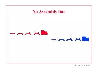
Ifetch Reg Exec Mem Wr Ifetch Reg Exec Mem Wr Ifetch Reg Exec Mem Wr Single Cycle vs. Pipeline Cycle 1 Cycle 2 Clk Single Cycle Implementation: Load Store Waste Pipeline Implementation: Load Store R-type Why pipeline ?
IFetch Dcd Exec Mem WB IFetch Dcd Exec Mem WB IFetch Dcd Exec Mem WB IFetch Dcd Exec Mem WB IFetch Dcd Exec Mem WB IFetch Dcd Exec Mem WB Pipelined Representation timing diagram Time Program Flow Your code
Pipelining: Performance • Pipeline: multiple inst. are overlapped in execution • Improve inst. throughput rather than inst. execution time • speedup = • pipe stage: balancing length of each stage with equal length, limited # pipe stages
Reg Reg Reg Reg Reg Reg Reg Reg Ifetch Ifetch Ifetch Ifetch DMem DMem DMem DMem ALU ALU ALU ALU Cycle 1 Cycle 2 Cycle 3 Cycle 4 Cycle 5 Cycle 6 Cycle 7 Visualizing Pipelining – clearer view Time (clock cycles) I n s t r. O r d e r
0 M u x 1 I F / I D E X / M E M M E M / W B A d d A d d 4 A d d r e s u l t S h i f t l e f t 2 n o i t A d d r e s s P C c u r t s n I I n s t r u c t i o n m e m o r y 0 0 W r i t e 3 2 Pipelined Datapath I D / E X R e a d r e g i s t e r 1 R e a d d a t a 1 R e a d Z e r o r e g i s t e r 2 R e g i s t e r s A L U R e a d A L U R e a d W r i t e A d d r e s s d a t a 2 1 r e s u l t d a t a r e g i s t e r M M u D a t a u W r i t e x m e m o r y x d a t a 1 d a t a 1 6 S i g n e x t e n d Must Add buffers between stages to maintain instruction information and results
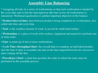
1 2 3 4 5 Load Ifetch Reg/Dec Exec Mem Wr 1 2 3 4 R-type Ifetch Reg/Dec Exec Wr Pipeline Rules • Each functional unit can only be used once per instruction • And at same stage for all instructions: • Load uses Register File’s Write Port during its 5th stage • R-type uses Register File’s Write Port during its 4th stage Introduce bypass stage for R-type so WB is also 5 th stage
Pipeline problems a.k.a hazards • Hazards: cause incorrect execution if next instruction launched • Structural hazards: Use of same hardware to do two different things at the same time • Data hazards: Instruction depends on result of prior instruction ; Data dependency • Control hazards: due to delay between instruction fetching and decisions about changes in control flow (branches and jumps).
Reg Reg Reg Reg Reg Reg Reg Reg Ifetch Ifetch Ifetch DMem DMem DMem ALU ALU ALU ALU Ifetch Structural Hazard 1.Structural Hazard Example I: Same Register Filecycle 5: Load instruction and Instr 3 use same reg. file Time (clock cycles) Cycle 1 Cycle 2 Cycle 3 Cycle 4 Cycle 5 Cycle 6 Cycle 7 I n s t r. O r d e r Load DMem Instr 1 Instr 2 Instr 3 Solution: Write in 1st half of clock Read in 2nd half Instr 4
Resolving structural hazards • Problem: simultaneous use of same hardware by two different stages • Solution 1: Wait - • Detect hazard • stall • Serious. Poor choice • Solution 2: Redesign pipeline, add hardware
MEM/WB ID/EX EX/MEM IF/ID Adder 4 Address ALU Eliminating Structural Hazards Separate Reg File Read / Write ports Next PC MUX Next SEQ PC Next SEQ PC Zero? RS1 Reg File MUX Instr Cache RS2 Data Cache MUX MUX Sign Extend WB Data Imm Datapath RD RD RD Control Path
2. Data Hazards: Data Dependency, most common • Read After Write (RAW)InstrJ tries to read operand before InstrI writes it • Caused by a “Data Dependence” (in compiler nomenclature). I: add r1,r2,r3 J: sub r4,r1,r3 Common in every modern CPU
Time (in clock cycles) CC 1 CC 2 CC 3 CC 4 CC 5 CC 6 CC 7 CC 8 CC 9 10 10 10 10 10/Ð20 Ð20 Ð20 Ð20 Ð20 Program execution ,$1, $3 IM Reg Sub $2 and $12, $5, $2 IM Reg IM DM Reg or $13, $6, $2 Reg , IM DM Reg add $14, $2,$2 IM DM Reg Data Hazard Example register $2: Reg DM DM Reg Reg sw $15, 100 ($2) Reg Wrong (old) data fetched from registers!
S/W: Compiler can eliminate / Minimize Data HazardsCode Scheduling • Move independent inst. to eliminate data hazards and fill in bubblesI1 and $18, $9, $10 I2 sub $2, $1, $3 I3 and $12, $2, $5 I4 or $13, $6,$2 I5 add $14, $2, $2 I6 sw $15, 100($2) I7 sub $16, $7, $8 I8 add $17, $8, $9 • RAW dependence b/w I2 and I3, I4, I5
Time (in clock cycles) CC 1 CC 2 CC 3 CC 4 CC 5 CC 6 CC 7 CC 8 CC 9 Value of register $2 : 10 10 10 10 10/Ð20 Ð20 Ð20 Ð20 Ð20 Value of EX/MEM : X X X Ð20 X X X X X Value of MEM/WB : X X X X Ð20 X X X X Program execution order (in instructions) $2 , $1, $3 sub IM Reg DM Reg and $12, $2 , $5 IM Reg DM Reg $2 or $13, $6, IM Reg DM Reg $2 , $2 IM Reg DM Reg add $14, sw $15, 100 ($2) IM Reg DM Reg Data hazard Architecture solution: Forwarding
ID/EX EX/MEM MEM/WB Registers ALU Data memory M u x a. No forwarding ID/EX EX/MEM MEM/WB M u x Registers ForwardA ALU M Data u memory M x u x Rs ForwardB Rt Rt M EX/MEM.RegisterRd u Rd x Forwarding MEM/WB.RegisterRd unit b. With forwarding Hardware before forwarding Hardware With Forwarding additions
ID/EX WB EX/MEM M WB Control MEM/WB EX M WB IF/ID M u X Instruction Registers Data Instruction ALU PC memory M memory u x M u x IF/ID.RegisterRs Rs IF/ID.RegisterRt Rt IF/ID.RegisterRt Rt EX/MEM.RegisterRd M u IF/ID.RegisterRd Rd x Forwarding MEM/WB.RegisterRd unit Modified datapath with forwarding
Time (in clock cycles) Program CC 1 CC 2 CC 3 CC 4 CC 5 CC 6 CC 7 CC 8 CC 9 execution order (in instructions) Reg $2 , 20($1) IM DM Reg lw $4 , $2 , $5 and IM Reg DM Reg or $8, $2 , $6 IM Reg DM Reg add $9, $4 , $2 IM Reg DM Reg slt $1, $6, $7 IM DM Reg Reg Data Hazard Even with Forwarding(Load – immediate Use)
Program Time (in clock cycles) execution CC 1 CC 2 CC 3 CC 4 CC 5 CC 6 CC 7 CC 8 CC 9 CC 10 order (in instructions) Reg DM Reg IM $2 , 20($1) lw Reg DM IM Reg Reg $4 , $2 , $5 and Reg or $8, $2 , $6 DM Reg IM IM bubble add $9, $4 , $2 Reg IM DM Reg slt $1, $6, $7 Reg DM IM Reg Load – immediate use stall And $4, $2, $5 stalled one cycle
Reg Reg Reg Reg Reg Reg Reg Reg Reg Reg ALU ALU ALU ALU ALU Ifetch Ifetch Ifetch Ifetch Ifetch DMem DMem DMem DMem DMem I n s t r. O r d e r add r1,r2,r3 lw r4, 0(r1) sw r4,12(r1) or r8,r6,r9 xor r10,r9,r11 Forwarding to Avoid LW-SW Data Hazard Time (clock cycles)
Resolving load hazards Summary • Adding hardware. Forwarding memory data to pipeline minimizes stalls. • Compilation / code scheduling techniques
Time (in clock cycles) Program execution CC 1 CC 2 CC 3 CC 4 CC 5 CC 6 CC 7 CC 8 CC 9 order (in instructions) 40 beq $1, $3, 7 IM Reg DM Reg 44 and $12, $2, $5 IM Reg DM Reg 48 or $13, $6, $2 IM Reg DM Reg 52 add $14, $2, $2 IM Reg DM Reg 72 lw $4, 50($7) DM Reg Reg IM Control Hazard - Branches=> Three Stage MIPS Stall - branch penalty
Example: Branch Stall Impact • If 20% branch, Stall 3 cycles significant • Two part solution: • Determine branch taken or not sooner, AND • Compute taken branch address earlier • MIPS branch tests if register = 0 or 0 • MIPS Solution: • Move Zero test to ID/RF stage • Adder to calculate new PC in ID/RF stage • 1 clock cycle penalty for branch versus 3
IF.Flush Hazard detection unit ID/EX M u x WB EX/MEM M M WB u Control MEM/WB x 0 EX M WB IF/ID 4 Shift left 2 M u x = Registers Data Instruction ALU PC memory M memory u x M u x Sign extend M u x Forwarding unit Datapath with branch flush hardware Detects Load – imm use, needs Rt from LW, Rs, Rt from dependent inst.r
I n s t r. O r d e r Time (clock cycles) Mem Reg Reg Add Mem ALU Mem Reg Reg Beq Mem ALU Load Lost potential Mem Reg Reg Mem ALU Control Hazard Solution #1: Stall • Stall: wait until decision is clear • Impact: 2 lost cycles (i.e. 3 clock cycles per branch instruction) => slow • Move decision to end of decode • save 1 cycle per branch
Static Branch Hazard Alternatives #1: Stall (WAIT) until branch direction is clear #2: Predict Branch Not Taken • Execute successor instructions in sequence • “Squash” instructions in pipeline if branch actually taken • Advantage of late pipeline state update • 47% MIPS branches not taken on average • PC+4 already calculated, so use it to get next instruction
MIPS with Predict Not Taken Prediction correct Prediction incorrect
I n s t r. O r d e r Time (clock cycles) Mem Reg Reg Add Mem ALU Mem Reg Reg Beq Mem ALU Misc Mem Mem Reg Reg ALU Load Mem Mem Reg Reg ALU Control Hazard Solution #3: Delayed Branch • Delayed Branch: Redefine branch behavior (takes place after next instruction) • Impact: 0 clock cycles per branch instruction if can find instruction to put in “slot” ( 50% of time) • As launch more instruction per clock cycle, less useful
Delayed Branch • Where to get instructions to fill branch delay slot? • Before branch instruction • From the target address: only valuable when branch taken • From fall through: only valuable when branch not taken • Canceling branches allow more slots to be filled • Compiler effectiveness for single branch delay slot: • Fills about 60% of branch delay slots • About 80% of instructions executed in branch delay slots useful in computation • About 50% (60% x 80%) of slots usefully filled • Delayed Branch downside: if 7-8 stage pipelines, multiple instructions issued per clock (superscalar)
a. From before b. From target c. From fall through sub $t4, $t5, $t6 add $s1, $s2, $s3 add $s1, $s2, $s3 É if $s2 = 0 then if $s1 = 0 then add $s1, $s2, $s3 Delay slot Delay slot if $s1 = 0 then sub $t4, $t5, $t6 Delay slot Becomes Becomes Becomes add $s1, $s2, $s3 if $s1 = 0 then if $s2 = 0 then add $s1, $s2, $s3 sub $t4, $t5, $t6 add $s1, $s2, $s3 if $s1 = 0 then sub $t4, $t5, $t6 Scheduling the branch Delay slot
More-Realistic Branch Prediction • Static branch prediction • Based on typical branch behavior • Example: loop and if-statement branches • Predict backward branches taken • Predict forward branches not taken • Dynamic branch prediction • Hardware measures actual branch behavior • e.g., record recent history of each branch • Assume future behavior will continue the trend • When wrong, stall while re-fetching, and update history • Used in all modern CPUs; eg core …
Dynamic Branch Prediction Problem History Information • Incoming stream of addresses • Fast outgoing stream of predictions • Correction information returned from pipeline Branch Predictor Incoming Branches { Address } Prediction { Address, Value } Corrections { Address, Value }
Dynamic Branch Prediction • branch penalty is huge I deep superscalar pipelines • dynamic prediction • Branch prediction buffer (aka branch history table) • Indexed by branch address • Stores outcome (taken/not taken) • To execute a branch • Check table • Start fetching from fall-through or target • If wrong, flush pipeline and flip prediction
1-Bit Predictor: Shortcoming outer: … …inner: … … beq …, …, inner … beq …, …, outer • Inner loop branches mispredicted twice! • Mispredict taken on last iteration of inner loop • Mispredict not taken on first iteration of inner loop
2-Bit Predictor • Only change prediction on two successive mispredictions
Branch PC Predicted PC BTB: Branch Address at Same Time as Prediction • Branch Target Buffer (BTB): Address of branch index to get prediction AND branch address (if taken) PC of instruction FETCH Yes: instruction is branch and use predicted PC as next PC =? prediction state Bits (2 bits) No: branch not predicted, proceed normally (Next PC = PC+4) Only predicted taken branches and jumps held in BTB Next PC determined before branch fetched and decoded later: check prediction, if wrong kill instruction, update BPb
Pipeline ControlRTL description IR <= mem[PC]; PC <= PC + 4 • We have 5 stages. What needs to be controlled in each stage? • Instruction Fetch and PC Increment • Instruction Decode / Register Fetch • Execution • Memory Stage • Write Back • Generate all control signals in the ID stage and pipeline them A <= Reg[IRrs]; B <= Reg[IRrt] rslt <= A opIRop B WB <= rslt; Or WB <= mem(rslt) Reg[IRrd] <= WB
PCSrc 0 M u x 1 IF/ID ID/EX EX/MEM MEM/WB Add Add Add 4 result Branch Shift RegWrite left 2 Read MemWrite register 1 PC Address ead Instruction data 1 Read ALUSrc MemtoReg Zero Zero register 2 Instruction Registers ALU Read ALU memory 0 Read Write data 2 Address 1 result register M data M u Data u Write x memory x data 1 0 Write data Instruction 6 [15Ð0] 16 32 Sign ALU MemRead extend control Instruction [20Ð16] 0 M ALUOp Instruction u [15Ð11] x 1 RegDst Pipelined datpath with control signals
Pipeline Control • control signals passed along with data
Exceptions and Interrupts - Review • “Unexpected” events change control flow • Exception • Arises within the CPU • e.g., undefined opcode, overflow, syscall, … • Interrupt • From an external I/O controller • Dealing with them without sacrificing performance is hard
Vectored Interrupts: Alternate Mechanism • Handler address determined by the cause • Example: • Undefined opcode: C000 0000 • Overflow: C000 0020 • …: C000 0040 • Instructions Jump to real handler