Download
1 / 17
170 likes | 237 Views
Explore methodological aspects and applications of one-dimensional, steady-state conduction without thermal energy generation. Analyze heat equation, temperature distribution, Fourier’s Law, boundary conditions, and thermal resistances in common geometries like plane walls, tube walls, and spherical shells. Gain insights into heat transfer coefficients, composite walls, convection, and thermal circuits in various scenarios.

E N D
One-Dimensional, Steady-StateConduction withoutThermal Energy Generation Chapter Three Sections 3.1 through 3.4
Methodology Methodology of a Conduction Analysis • Specify appropriate form of the heat equation. • Solve for the temperature distribution. • Apply Fourier’s Law to determine the heat flux. Simplest Case: One-Dimensional, Steady-State Conduction with No Thermal Energy Generation. • Common Geometries: • The Plane Wall: Described in rectangular (x) coordinate. Area perpendicular to direction of heat transfer is constant (independent of x). • The Tube Wall: Radial conduction through tube wall. • The Spherical Shell: Radial conduction through shell wall.
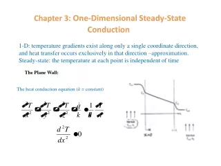
Heat Equation: (3.1) • Boundary Conditions: • Temperature Distribution for Constant : (3.3) The Plane Wall Plane Wall • Consider a plane wall between two fluids of different temperature: • Implications:
(3.5) (3.4) • Thermal Resistances and Thermal Circuits: Conduction in a plane wall: (3.6) Convection: (3.9) (3.12) (3.11) Plane Wall (cont.) • Heat Flux and Heat Rate: Thermal circuit for plane wall with adjoining fluids:
Radiation Resistance: (1.9) Plane Wall (cont.) • Thermal Resistance for Unit Surface Area: • Contact Resistance: Values depend on: Materials A and B, surface finishes, interstitial conditions, and contact pressure (Tables 3.1 and 3.2)
(3.14) • Overall Heat Transfer Coefficient (U) : A modified form of Newton’s Law of Cooling to encompass multiple resistances to heat transfer. (3.17) (3.19) Plane Wall (cont.) • Composite Wall with Negligible Contact Resistance:
Note departure from one-dimensional conditions for . • Circuits based on assumption of isothermal surfaces normal to x direction or adiabatic surfaces parallel to x direction provide approximations for . Plane Wall (cont.) • Series – Parallel Composite Wall:
The Tube Wall (3.23) What does the form of the heat equation tell us about the variation of with in the wall? How does vary with ? • Temperature Distribution for Constant : (3.26) Tube Wall • Heat Equation: Is the foregoing conclusion consistent with the energy conservation requirement?
Conduction Resistance: (3.28) Tube Wall (Cont.) • Heat Flux and Heat Rate: (3.27) Why is it inappropriate to base the thermal resistance on a unit surface area?
(3.30) But, U itself is tied to specification of an interface. (3.32) Tube Wall (Cont.) • Composite Wall with Negligible Contact Resistance
Spherical Shell What does the form of the heat equation tell us about the variation of with ? Is this result consistent with conservation of energy? How does vary with ? • Temperature Distribution for Constant : Spherical Shell • Heat Equation
(3.35) (3.36) Spherical Shell (cont.) • Heat flux, Heat Rate and Thermal Resistance: • Composite Shell:
Problem: Thermal Barrier Coating Problem 3.23: Assessment of thermal barrier coating (TBC) for protection of turbine blades. Determine maximum blade temperature with and without TBC. Schematic:
With a heat flux of the inner and outer surface temperatures of the Inconel are Problem: Thermal Barrier (Cont.) ANALYSIS: For a unit area, the total thermal resistance with the TBC is
Problem: Radioactive Waste Decay Problem 3.62: Suitability of a composite spherical shell for storing radioactive wastes in oceanic waters.