Download
1 / 18
180 likes | 341 Views
Explore methods to enhance heat transfer efficiency in one-dimensional steady-state conduction systems, focusing on composite cylindrical walls, extended surfaces like fins, and fin geometries. Learn how to calculate fin efficiency and make informed design choices for improved thermal performance.

E N D
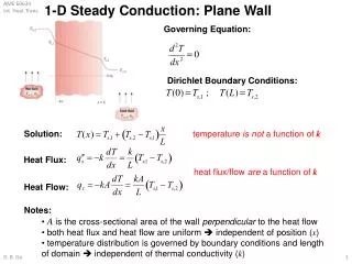
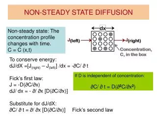
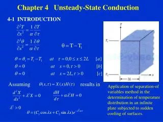
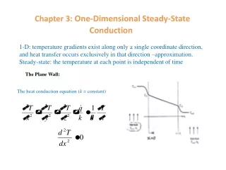
1-D: temperature gradients exist along only a single coordinate direction, and heat transfer occurs exclusively in that direction –approximation. Steady-state: the temperature at each point is independent of time Chapter 3:One-Dimensional Steady-State Conduction The Plane Wall: The heat conduction equation (k = constant)
General solution: Thermal Resistance B.C.’s: T(0) =Ts,1, T(L) = Ts,2 = constant = constant Thermal Resistance: For conduction of electricity, Ohm’s law: I: electric current, E: electric potential, Re: electric resistance thermal resistance for conduction An analogy
Thermal Resistance In the case that Ts,1 and Ts,2 are unknown, and T,1 and T,2 are known, an energy balance at x = 0 gives (1) at x = L, (2) In the wall, (3)
Thermal Resistance (1)+ (2)+ (3) on each side: Let
Thermal Resistance Restrictions: 1-D. S.S., no heat source or sink. The composite wall:
Radial Systems – the cylinder A common example is the hollow cylinder:
Radial Systems – the cylinder Eq. (2.24): Integrate once: B.C.’s: = constant
Radial Systems – the cylinder But Composite cylindrical wall:
Heat Transfer from Extended Surfaces Heat transfer between a solid and an adjoining fluid: • To increase q for a fixed Ts: • Increase velocity to increase h (too costly, increased blower or pumping power consumption) • Reduce , impractical 3. Increase A fins, for low h and smaller Applications: Car radiators, heating units, liquid-gas, or gas-gas heat exchangers, boilers, and air-cooled engines, …
Extended Surfaces (Fins, Pins, or Spines) Assumptions: 1. The transversal characteristic length, say the thickness of the fin, is small compared to the axial length, <<1 2.The thermal conductivity is constant 3.The heat transfer coefficient is the averaged value 4.Steady state
Extended Surfaces (Fins, Pins, or Spines) Let excess temperature, P -- perimeter This is a ODE, exact solutions exist for some functions Fins of uniform cross-sectional area, A = Ac = constant
Extended Surfaces (Fins, Pins, or Spines) The general solution is of the form: C1, C2, -- two B.C.’s needed Solve for C1 and C2 using the two B.C.’s The hyperbolic functions:
Fin Performance Fin effectiveness -- ratio of the fin heat transfer rate to heat transfer rate that would exist without the fin: The use of fins may rarely be justified unless Subject to the infinite fin condition and for a fin of uniform cross section (case D) (when heat transfer coefficient is small); (use of metals); (thin, closely spaced fins are preferred) The above equation provides an upper limit for For more accurate evaluation of the fin effectiveness, the relation associated with convection B.C.’s should be used (Table 3.4). In this case, the effectiveness is a more complicated function of M, mL, h and k, and the relation between these variables are not as obvious as Case D.
Fin efficiency have fins or have no fins? Once having fins, what fins are better? What’s the best geometry for the fin? by assuming the entire fin surface were at the base temperature, Af: fin surface area Not the base area Fin efficiency : good for a practical comparison basis under constant Not good for fin geometry study because the comparison is based on “having fins” and “having no fins” : good for fin design, have a common comparison basis Af Accurate design should be based on the convection B.C. –Case A, table 3.4, but the relation is too cumbersome An approximate, yet accurate by using the adiabatic tip result (case B, table 3.4) with a corrected fin length,
Fin efficiency Errors are negligible if (h/k) < 0.0625 If W >> t, P =2W and Ac = Wt Multiplying the numerator and denominator by and introducing a corrected fin profile area AP = Lct (different from Ac!), it follows that AP: fin volume per unit width fin weight per unit width, an important design criterion
Fin efficiency Figures 3.18 – 3.19 present comparison between different fin geometries and some analytical solutions for fin efficiency are given in Table 3.5 A straight triangular fin is attractive, less volume, less costly than the parabolic profile
Overall surface efficiency: Once we know by solving differential equations or through the charts, Overall surface efficiency: where qt and At are the total heat rate and exposed area of finned and unfinned surfaces. For constant base Tb or where is the efficiency of a single fin and N is the number of fins The efficiency is based on the same h for both finned and unfinned surfaces