Download
1 / 32
530 likes | 1.21k Views
Chapter 2: Steady-State One-Dimensional Heat Conduction. 2.1 …………. Conduction through a plane wall & composite wall 2.2 …………. Conduction from fluid to fluid through a composite wall 2.3 …………. Overall Heat Transfer Coefficient

E N D
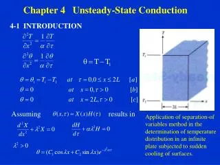
Chapter 2: Steady-State One-Dimensional Heat Conduction 2.1 …………. Conduction through a plane wall & composite wall 2.2 …………. Conduction from fluid to fluid through a composite wall 2.3 …………. Overall Heat Transfer Coefficient 2.4 …………. Conduction through a hollow cylinder & composite cylinder 2.5 …………. Conduction through a sphere 2.6 …………. Boundary and Initial Condition 2.7 …………. Critical thickness of Insulation
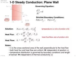
2.1 … Steady State Conduction through a plane wall . Q k T1 . Q L Thermal resistance (in k/W) (which opposing heat flow) T2 T1 x ME 259
Electrical Analogy Thermal Analogy to Ohm’s Law OHM’s LAW :Flow of Electricity V=IR elect Temp Drop=Heat Flow × Resistance Voltage Drop = Current flow ×Resistance
Steady State Conduction through a composite wall . . Q Q B C A T1 T2 Q T3 kA T4 kB kA kB kC kC x ΔxA ΔxB ΔxC
T∞,1 …. . . . . . .. .. .. . . . . .. . .. . . . . .. . . . . . . . . .. .. . . … . . . . . . .. . . . . . . . . . . . . . . . . Cold fluid k Ts,1 .. . . . . . . . . . .. . . . . . . . . . . . . . Ts,2 T∞,2 Hot fluid x=L x=0 1 L 1 A A A h h k 2 1 1 D Heat flow from fluid to fluid through plain wall T∞,1 Ts,1 Ts,2 T∞,2 qx (Thermal Resistance )
T∞,1 A B C h1 K A K B K C h2 T∞,2 T∞,1 T∞,2 L A L B L C q x 1 1 A A h h 1 2 2.2…1-D Heat flow from fluid to fluid through composite wall
Parallel composite • The heat transfer rate in the network is parallel • Alternatively, the heat transfer rate can be calculated as the sum of heat transfer rates in the individual materials, i.e.
Series composite • Contact Resistance • In composite systems, the interface between two layers is usually not perfect. This is due to surface roughness effect. • Contact spots between the two layers are interspersed with gaps that are, in most instances, air filled. • The additional resistance between the two layers, called thermal contact resistance Rt, results in temperature drop across the interface. • Thermal contact resistance is dependent upon the solid materials, surface roughness, contact pressure, temperature, and interfacial fluid.
2.3 … Overall Heat Transfer Coefficient A modified form of Newton’s Law of Cooling to encompass multiple resistances to heat transfer. In above equation, Overall heat transfer coefficient
2.4 … Conduction through hollow cylinder Consider a hollow cylinder of length L (shown below), whose inner and outer surfaces are exposed to fluids at different temperatures. The system is analyzed by the standard method as follows:
Conduction through hollow cylinder (continue….) • For steady-state conditions with no heat generation, the heat equation for the system is • The boundary conditions are • Integrating the heat equation (assuming constant k) and using the boundary conditions yield Therefore, the temperature distribution associated with radial conduction through a cylindrical wall is logarithmic. The heat transfer rate is obtained by using the temperature distribution with Fourier’s law: where,
Conduction through hollow cylinder (continue….) For pure conduction, we considered resistances in series in which our primary interest was in the temperatures at the inner and outer walls (not the interior walls). For convection, a similar principle arises. Consider a pipe filled with hot fluid at temperature T1. Define intermediate temperatures as follows: T1 T2 Insulation Air T5 Hot liquid T3 Pipe T4
Conduction through Composite Cylinder Consider a composite cylindrical wall of length L shown below.
Conduction through Composite Cylinder (continue) • Assumption: Neglecting interfacial contact resistances • The heat transfer rate may be expressed as • Above equation may be expressed in terms of an overall heat transfer coefficient as • If U is defined in terms of the inside area A1, above equations may be equated to yield Note: Similar equations could be written for U2, U3, etc.
Conduction through Composite Cylinder (continue) For pure conduction, we considered resistances in series in which our primary interest was in the temperatures at the inner and outer walls (not the interior walls). For convection, a similar principle arises. Consider a pipe filled with hot fluid at temperature T1. Define intermediate temperatures as follows: T1 T2 Insulation Air T5 Hot liquid T3 Pipe T4
The heat transfer rate for each "step": q1->2 = conduction or convection? q2->3 = conduction or convection? q3->4 = conduction or convection? q4->5 = conduction or convection? Convection Conduction Conduction Convection
(T5–T1) = (T5-T4) + (T4-T3) + (T3-T2) + (T2-T1) Q = UoAo (T5-T1) Q = hoAo (T5-T4) Outside film (air) Q = kinsul Alm (T4-T3) / Drinsul Insulation Q = kpipe Alm (T3-T2) / Drpipe Pipe Q = hiAi (T2-T1) Inside film (hot liquid)
(T5–T1) = (T5-T4) + (T4-T3) + (T3-T2) + (T2-T1) (T5-T1) = Q / UoAo Similar substitutions yield:
With U known, it is a simple matter to calculate the overall heat transfer rate given the total temperature difference. Note that we have used the symbol Uo because the overall heat transfer coefficient was defined with respect to the outside area (Ao) of the pipe. This is the most common practice. We could equally have defined 1/Ui or UiAi. In this case, we would use Ai as the basis for calculations. In either case, the values of U would be slightly different, but UA and hence q are the same.
Equation for 1/Ui • Rule of thumb: If the ratio of Do/Di is less than 1.5, then the arithmetic average of • Do and Di is roughly equal to the log mean average (good for ANY log mean average). • Limiting Resistance: • A very useful concept in heat transfer is that of limiting resistance. • What is limiting resistance? • What would the limiting resistance be for a hot liquid flowing inside an uninsulated • pipe? • How would you increase the heat transfer rate?
2.5…Conduction through Sphere • Heat Equation • Temperature Distribution for Constant k:
Heat flux, Heat Rate and Thermal Resistance: • Composite Shell:
2.6… Boundary and Initial Conditions • Heat equation is a differential equation: • Second order in spatial coordinates: Need 2 boundary conditions • First order in time: Need 1 initial condition • Boundary Conditions • B.C. of first kind (Dirichlet condition): Ts Constant Surface Temperature At x=0, T(x,t)=T(0,t)=Ts T(x,t) x x=0
qx” T(x,t) x • Adiabatic surface qx”=0 T(x,t) x Boundary and Initial Conditions (Continue…) • B.C. of second kind (Neumann condition): Constant heat flux at the surface • Finite heat flux = qs”
q”convection = q”conduction T(0,t) T(x,t) x Boundary and Initial Conditions (continue…) 3) B.C. of third kind: When convective heat transfer occurs at the surface
2.7…Critical Radius of Insulation • We know that by adding more insulation to a wall always decreases heat transfer. • This is expected, since the heat transfer area A is constant, and adding insulation will always increase the thermal resistance of the wall without affecting the convection resistance. • However, adding insulation to a cylindrical piece or a spherical shell, is a different matter. • The additional insulation increases the conduction resistance of the insulation layer but it also decreases the convection resistance of the surface because of the increase in the outer surface area for convection. • Therefore, the heat transfer from the pipe may increase or decrease, depending on which effect dominates. • A critical radius (rcr) exists for radial systems, where: • adding insulation up to this radius will increase heat transfer • adding insulation beyond this radius will decrease heat transfer • For cylindrical systems, rcr = kins/h • For spherical systems, rcr = 2kins/h
Critical Radius of Insulation (continue….) Consider a cylindrical pipe, where, r1-- outer radius T1 -- constant outer surface temperature k-- thermal conductivity of the insulation r2 -- outer radius - temperature of surrounding medium h - convection heat transfer coefficient Insulated Cylindrical Pipe
Critical Radius of Insulation (continue….) The rate of heat transfer from the insulated pipe to the surrounding air can be expressed as The variation of heat transfer rate with the outer radius of insulation r2 is plotted in Figure 2.16. The value of r2 at which heat transfer rate reaches maximum is determined from the requirement that (zero slope). Performing the differentiation and solving for r2 gives us the critical radius of insulation for a cylindrical body to be NOTE: The rate of heat transfer from the cylinder increases with the addition of insulation for r2< rcr, reaches a maximum when r2= rcr, and starts to decrease for r2> rcr. Thus, insulating the pipe may actually increase the rate of heat transfer from the pipe instead of decreasing it when r2< rcr.
R t o t good for electrical cables good for steam pipes etc. R c r=k/h r0 Critical Radius of Insulation (continue….) Variation Of Heat Transfer Rate With Radius
One-Dimensional Steady State Solutions to the Heat Equation With No Generation