Download
1 / 34
760 likes | 1.63k Views
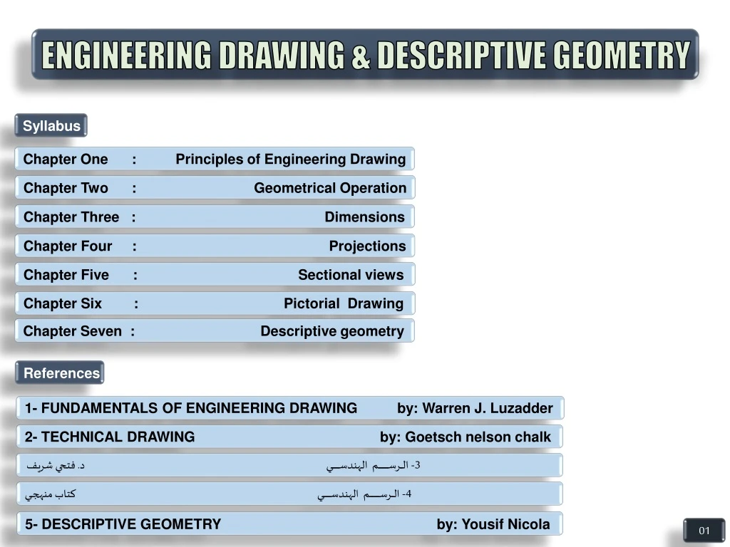
ENGINEERING DRAWING & DESCRIPTIVE GEOMETRY. Syllabus. Chapter One : Principles of Engineering Drawing. Chapter Two : Geometrical Operation. Chapter Three : Dimensions.

E N D
ENGINEERING DRAWING & DESCRIPTIVE GEOMETRY Syllabus • Chapter One : Principles of Engineering Drawing • Chapter Two : Geometrical Operation • Chapter Three : Dimensions • Chapter Four : Projections • Chapter Five : Sectional views • Chapter Six : Pictorial Drawing • Chapter Seven : Descriptive geometry References 1- FUNDAMENTALS OF ENGINEERING DRAWING by: Warren J. Luzadder 2- TECHNICAL DRAWING by: Goetsch nelson chalk 3- الــــرســــــــــــــــــــم الهندســـــــــــــــي د. فتحي شريف 4- الــــرســــــــــــــــــــم الهندســـــــــــــــي كتاب منهجـــي 5- DESCRIPTIVE GEOMETRY by: Yousif Nicola 01
CHAPTER ONE : PRINCIPLES OF ENGINEERING DRAWING 1.1 : INTRODUCTION • Engineering drawing is a formal and precise way of communicating • Information about the shape, size, features and precision of physical objects. • Drawing is the universal language of engineering. 1.2 : BASIC INSTRUMENTS 1.2.1 : Drawing Sheets A4 A4 A2 Symbol Sheet Dimensions ----------- --------------------------- A0 ( 1089 X 841 ) mm A1 ( 841 X 594 ) mm A2 ( 594 X 420 ) mm A3 ( 420 X 297 ) mm A4 ( 297 X 210 ) mm A5 ( 210 X 148 ) mm A3 A0 A1 02
1.2.2 : T-SQUARE &TRINGLES 450 600 900 300 450 900 900 T - SQUARE 450 Triangle 300 and 600Triangle 1.2.3 : COMPASS AND DIVIDERS 03
1.2.4 : PENCILS AND ERASERS WOODEN PENCILS ERASER MECHANICAL PENCILS ( 0.5 OR 0.7 ) mm 1.2.5 : TAPES AND SCALES 1.2.6 : PROTRACTOR 04
1.3 : LETTERING • In Engineering drawing there are dimensions and notes that are written on • the sheet and must be clear , have convenient size and easy to read, letters and • Numbers must be written in Engineering way. 750 6 mm 1.4 : DRAWING SHEET PAPER 12 cm 50 cm 2 cm 1cm الاســـــــــــم بالـــعـــربـــــــي 1 cm 6 cm 35 cm 1 cm Tittle block 1 cm 1 cm Tittle block 05
10 cm 1.5 : TYPES OF LINES Visible outline ( Full Line ) A A Hidden Line ( Dashed Line ) Break Line Cutting Plane Center Line Extension Line 10 cm Dimension Line Section lining SECTION A-A Note: 1- For lines have spacing, the space should be approximately (1 ) mm. 2- For Hidden line the dashes must be approximately (2 – 8 ) mm. 3- For Center line the long dashes must be approximately (5 – 20 ) mm and the dashes must be approximately (2 ) mm . 06
1.6 : SCALES The Scales used in engineering practice are : Reducing scale Enlarging scale Full size scale 1 : 5 1 : 10 10 : 1 1 : 20 5 : 1 1 : 1 1 : 25 2 : 1 1 : 50 1 : 100 07
CHAPTER TWO: GEOMETRICAL OPERATION 2.1 : INTRODUCTION • Geometrical operation means drawing engineering shapes using the • drawing instruments only, without calculation. 2.2 : GEOMETRICAL OPERATIONS Most geometrical operation used for engineering drawing consist of The following operations : 2.2.1 : BISECTING A STRIGHT LINE D Bisector line B Given : line AB R R 1-Draw two arcs with R > AB/2 from Point A & B to intersect in C & D A 2- Draw a straight line from C to D Which is a bisector line C 12
2.2.2 : DIVIDING A STRAIGHT LINE IN TO A GIVEN NUMBER OF EQUAL PARTS Given : Line AB ( 5 Parts ) C 1- Draw an auxiliary line like BC with a convenient angle with AB. B 2- locate on BC the 5 equal part by divider with any convenient dimension. A 3- Draw line AC. 4- Draw divider lines from located point on BC Parallel to AC 2.2.3 : DRAWING A STRAIGHT LINE PARALLEL TO ANOTHER LINE Given : Straight line , distance AB 1- In any two points on a straight line ( have enough Distance from each other ) draw two arcs with R=AB R=AB 2- Draw a line tangent to Two arcs. R=AB 13
2.2.4 : DRAWING A STRAIGHT LINE // TO ANOTHER USIG T-SQUARE & TRIANGLE Given : Straight line , Given distance 1- Put the triangle exactly on the given line 2- Put the T-square beside the triangle , Hold the T- square & move the triangle To the desired location . 2.2.5 : BISECTING AN ANGLE A Given : Line AB , BC and angle ABC F 1- Draw an arc with a convenient radius (R1) from B to intersect AB & CB from D & E R2 D C R2 2- From D & E Draw an arc ( R2 ) to intersect in F E R1 B 3- Draw BF Which is the bisector line of angle. 14
2.2.6 : DRAWING A TRIANGLE WITH KNOWING THE THREE SIDES C B A Given : Triangle sides C B 1- Draw one side for Example AB R2 C A R1 2- From two points A & B draw Two arcs R1 = CA & R2 = BC to Intersect in C B A 3- Draw AC & BC to complete the Triangle D 2.2.7 : DRAWING A REGULAR PENTAGON Given : One side length of pentagon AB R=AB R=AB 1- Bisect AB & Find Middle of AB ( O ) 2- Draw AF = AB ( AF is perpendicular to AB ) F E C 3- From ( O ) draw an arc R1 = OF to intersect With the extension of AB in ( G ) . R2=GB R2=GB 4- From A & B Draw two arcs R2 = GB to Intersect in D R1=OF 5- From ( D ) Draw two arcs R=AB to Intersect with previous drawn Arc R2 In two Points E and C B A O G 6- Draw lines AB,BC,CD,DE and EA to Complete the Pentagon 15
2.2.8 : DRAWING HEXAGON INSIDE THE CIRCLE B C Given : Circle Radius = R D A R R 1- From two points A & D draw two arcs with radius =R To intersect with circle in points F,B,E and C R 2- Draw lines AB,BC,CD,DE,EF and FA to complete the Hexagon. E F D R=DM 2.2.9 : DRAWING PENTAGON INSIDE THE CIRCLE Given : Circle with diameter = KL R1=DN C 1- Bisect line OL in ( N ) E O L K 2- From N draw an arc with radius R1 = DN to Intersect with the horizontal center line in M N M R=DM 3- Divide the circle to five equal parts by Distance = DM B A 4- Draw line AB , BC , CD , DE , EA to Complete the pentagon. 16
D E 2.2.10 : DRAWING HEXAGON WITH KNOWING ONE SIDE Given : One side length AB. F C 1- Using T-square and ( 30 & 60 ) degree triangle Draw AF & BC ( AF = BC = AB ). 2- From two points F and C Draw CD and EF (CD = EF = AB) then draw DE to complete the Hexagon A B N 2.2.11 : DIVIDING A CIRCLE IN TO SEVEN EQUAL PARTS Given : Circle with Diameter = AB 1- Draw arc with R = OA ( From A) to cut circle in N. O B A R=OA 2- Draw line NC ( NC is perpendicular to AB in C ) C 3- Open the compass by distance = NC to divide The circle in to seven equal parts. 17
2.2.12 : DRAWING AN OCTAGON Given : Distance between two sides 1- Draw a circle with Diameter = Distance Between two parallel sides 2- Using T-square and 45 degree triangle Draw other sides tangent to the circle as Shown. C 1 R 2.2.13 : DIVIDING CIRCLE INTO 8 EQUAL PARTS 8 2 Given : Circle with radius = R R 1- Draw the horizontal and vertical center lines Dividing circle into 4 equal parts. O 3 7 2- From two points 1 & 3 draw two arcs with A convenient radius to intersect in C 4 6 3- Draw OC and extend it to cut circle in 6 & 2 4- By the same procedure find points 8 and 4 5 18
2.2.14 : DRAWING AN ARC TANGENT TO TWO CROSSED STRAIGHT LINE R Given : Two lines crossed by an angle and arc radius = R T1 1- Draw the two parallel lines by distance R to Intersect in O. R 2- From ( O ) draw the two perpendicular Lines finding T1 and T2 R O 3- From ( O ) draw an arc by radius = R Starting from T1 to T2. R T2 2.2.15 : DRAWING AN ARC TANGENT TO ANOTHER ARC AND ALSO TAGENT TO A STRAIGHT LINE R O Given : An Arc and a straight line 1- Draw parallel line for the given line by ( r ) R R+r 2- Draw an arc From ( O ) by radius ( R + r ) , N is the intersection point of arc and line. T2 3- From ( N ) draw perpendicular line of given Line and find T1 N r 4- Draw ON and find tangent point T2. r T1 5- Draw arc with radius = r from center point N Starting from T1 and T2. r 19
2.2.16 : DRAWING AN ARC TANGENT TO TWO ARCS There are three cases to draw an arc tangent to two other arcs A: OUT TO OUT CASE Given: Two arcs with R1&R2 From O1&O2 and R 1- Draw to arcs from O1 with radius ( R+R1 ) And from O2 with radius ( R+R2 ) and find O 2- Draw OO1 and OO2 to find the two Tangent points T1 and T2 R2+R 3- From O draw an arc with radius R Starting from T2 to T1 R1+R R2 R1 O1 O2 T1 T2 R O 20
B: IN TO IN CASE Given: Two arcs with R1 & R2 From O1 & O2 and R 1- Draw to arcs from O1 with radius ( R-R1 ) And from O2 with radius ( R-R2) and find O 2- Draw OO1 and OO2 and extend it to find the two Tangent points T1 and T2 3- From O draw an arc with radius R Starting from T2 to T1 T2 T1 R-R1 R2 R1 R-R2 O2 O1 R O 21
C: IN TO OUT CASE Given: Two arcs with R1 & R2 From O1 & O2 and R 1- Draw to arcs from O1 with radius ( R-R1 ) And from O2 with radius ( R+R2) and find O 2- Draw OO1 and extend it to find T1 and OO2 To find the tangent point T2 3- From O draw an arc with radius R Starting from T2 to T1 T1 R2 R1 R O2 O1 R-R1 T2 R+R2 O 22
C A B D 2-2-17: DRAWING ELLIPS Draw the Two Axis AB and CD Draw from Origin an arc with r = OA to intersect with extension Line DC in N ( AO = NO) O2 N Draw Line AC r=CN From point C Draw an Arc with r = CN to cut Line AC in M ( CM = CN ) M r=OA O O1 O1 Draw a Bisector line to AM to Intersect with AB in O1 and Intersect with CD ( extension Of CD ) in O2 r=O1A R = O2C Find O1 & O2 of other Sides Using 4-Center Method Draw An Ellipse R = O2C , r = O1A O2 23
CHAPTER THREE : DIMENSIONS 3.1 : INTRODUCTION • A detail drawing, in addition to giving the shape of a part, must furnish • information such as the distance between surfaces, location of holes, kind of • finish, type of material and number required. 3.2 : THEORY OF DIMENTIONING • Any part may be dimensioned easily and systematically by dividing it • into simple geometric solid. Even complicated parts, when analyzed, are • usually found to be composed principally of Cylinders, Pyramids, Prisms…… 3.2.1 : SIZE DIMENSION AND LOCATION DIMENSION • Size dimension (S) give the size • of a piece, component part. L S L L S S • Location dimension ( L ) fix the • relationshipof the component • part. S S S 27
3.3 : DIMENSIONS GEOMETRIC SHAPE S (Note) S S S S S S S S S S S S S S PRISM CYLINDER PYRAMID CONE 28
3.4 : DIMENSION COMPONENT Projection lines Dimension line and Arrow heads Dimension value 5 5 5 5 5 Oblique stroke Leader line Symbols 30 Notes ɸ 10 3.5 : NOTES 20 1- 20 20 20 20 20 20 2- 29
3- 7- 60O 90O 30O 4- 8 8- 5- For Leader lines S= ( 2 – 3 ) t t= line thickness 9- 6- For inclined dimension 20 3S 16 20 20 20 20 20 20 18 x x 20 18 16 20 S 20 20 30
10- 14- Don’t use object line as dimension line Don’t repeat the dimension 11- 15- For Cylindrical shape 12- 16- For arc dimension R3 R20 ɸ8 30 50 60 40 30 3 x 15 5 5 54 16 20 18 16 16 54 18 20 54 18 20 20 10 50 54 60 40 13- 17- 31
CHAPTERFOUR : PROJECTIONS 4.1 : INTRODUCTION • Projection is a method to represent the exact shape of an • Object on the plane. 4.2 : PROJECTION TYPE The two main type of the projection are ( Perspective projection and Orthographic projection ) 4.2.1 : PERSPECTIVE PROJECTION Projection plane Projecting line • In Perspective projection , the • Projecting line or visual rays converge • At a point. C’ C B’ B O D D’ A A’ 32
4.2.2 : ORTHOGRAPHIC PROJECTION • Orthographic projection or parallel • Projection is the projection system that • Engineers use for manufacturing and • Construction drawings, In which the • Projecting lines are parallel and • perpendicular to the projection plane. Projection plane Projecting line C’ C B’ B D’ D A’ A 4.3 : PROJECTION PLANES • 1- Horizontal Plane (H.P): • The projection on the Horizontal Plane called --------------- TOP VIEW (T.V) • 2- Vertical Plane (V.P): • The projection on the Vertical Plane called --------------- FRONT VIEW (F.V) • 3- Profile Plane (P.P): • The projection on the Profile Plane called --------------------SIDE VIEW (S.V) 33
FV SV TV 34
30 30 30 R20 15 30 30 20 25 15 60 FV SV 50 20 450 TV 35
36 37 38 39 36
40 41 42 43 37