Introduction to Descriptive Geometry
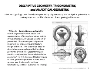
Introduction to Descriptive Geometry. ME114 COMPUTER AIDED ENGINEERING DRAWING II. Descriptive Geometry. Gaspard Monge(1746-1818), the father of descriptive geometry, developed a graphical protocol which creates three-dimensional virtual space on a two-dimensional plane.

Introduction to Descriptive Geometry
E N D
Presentation Transcript
Introduction to Descriptive Geometry ME114 COMPUTER AIDED ENGINEERING DRAWING II Descriptive Geometry Lectures
Descriptive Geometry • Gaspard Monge(1746-1818), the father of descriptive geometry, developed a graphical protocol which creates three-dimensional virtual space on a two-dimensional plane. • Monge became a scientific and mathematical aide to Napoleon during his reign as general and emperor of France. Descriptive Geometry Lectures
Definitions(1) Projective Geometry [1] • The branch of geometry dealing with the properties and invariants of geometric figures under projection. In older literature, projective geometry is sometimes called "higher geometry," "geometry of position," or "descriptive geometry" (Cremona 1960, pp. v-vi). Descriptive Geometry Lectures
Definitions(2) • Descriptive Geometry builds on the practice, evolved over centuries, of displaying two images of a single object simultaneously; one image is seen from one direction while a second image is seen from a direction 90° rotated (e.g., a "front" and a "side" view)[2]. Descriptive Geometry Lectures
Definitions(3) • Descriptive Geometry is a graphical communication system, concerned with describing space in a mathematical way, so that the geometrical objects and their interaction can be imagined and drawn[3]. Descriptive Geometry Lectures
Definitions(4) • Descriptive Geometry can be defined as the projection of three-dimensional figures onto a two-dimensional plane of paper in such a manner as to allow geometric manipulations to determine • lengths, • angles, • shapes • and other descriptive information concerning the figures [8]. Descriptive Geometry Lectures
Projection • When representing a 3-D object on the 2-D sheet of paper, the number of dimensions is reduced from 3 to 2. • The general process of reducing the number of dimensions of a given object is called projection [6]. Mainly, there are two different ways of doing this. According to the position of observer; • Perpective and • Parallel Projections. Descriptive Geometry Lectures
Perspective Projection Perspective(Central) projection is a type of drawing, or rendering, that graphically approximates on a planar (two-dimensional) surface (e.g. paper or painting canvas) the images of three-dimensional objects so as to approximate actual visual perception [4]. The projection or drawing upon the plane is produced by the points where projectors pierce the plane of projection (piercing points). In this case, where the observer is relatively close to the object, the projectors form a “cone” of projectors, resulting projection is known as a perspective projection[5]. Descriptive Geometry Lectures
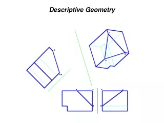
Parallel Projection • Descriptive geometry uses the image-creating technique of imaginary, parallel projectors emanating from an imaginary object and intersecting an imaginary plane of projection at right angles. The cumulative points of intersections create the desired image. Descriptive Geometry Lectures
Parallel Projection • Descriptive Geometry is based on Parallel Projection, in most cases parallel, orthogonal projection [6]. In particular, an orthogonal projection of a three-dimensional object onto a plane is obtained by intersections of lines drawn through all points of the object orthogonally to the plane of projection [7]. Descriptive Geometry Lectures
Orthographic projection • Orthographic projection is a means of representing a three-dimensional (3D) object in two dimensions (2D). It uses multiple views of the object, from points of view rotated about the object's center through increments of 90°. Descriptive Geometry Lectures
Orthographic projection • Equivalently, the views may be considered to be obtained by rotating the object about its center through increments of 90°. Descriptive Geometry Lectures
Protocols(1) • Project two images of an object into mutually perpendicular, arbitrary directions. Each image view accommodates three dimensions of space, two dimensions displayed as full-scale, mutually-perpendicular axes and one as an invisible (point view) axis receding(going back) into the image space (depth). Each of the two adjacent image views shares a full-scale view of one of the three dimensions of space. Descriptive Geometry Lectures
Protocols(2) • Either of these images may serve as the beginning point for a third projected view. The third view may begin a fourth projection, and on ad infinitum (continue forever). These sequential projections each represent a circuitous, 90° turn in space in order to view the object from a different direction. Descriptive Geometry Lectures
Protocols(3) • Each new projection utilizes a dimension in full scale that appears as point-view dimension in the previous view. To achieve the full-scale view of this dimension and accommodate it within the new view requires one to ignore the previous view and proceed to the second previous view where this dimension appears in full-scale. Descriptive Geometry Lectures
Protocols(4) • Each new view may be created by projecting into any of an infinite number of directions, perpendicular to the previous direction of projection. (Envision the many directions of the spokes of a wagon wheel each perpendicular to the direction of the axle.) • The result is one of stepping circuitously about an object in 90° turns and viewing the object from each step. Each new view is added as an additional view to an orthographic projection layout display and appears in an "unfolding of the glass box model". Descriptive Geometry Lectures
Protocols(5) • Aside from the Orthographic, six standard principal views (Front; Right Side; Left Side; Top; Bottom; Rear), descriptive geometry strives to yield three basic solution views: • the true length of a line (i.e., full size, not foreshortened), • the point view (end view) of a line, • and the true shape of a plane (i.e., full size to scale, or not foreshortened). Descriptive Geometry Lectures
Protocols(5 cont’d) • These often serve to determine the direction of projection for the subsequent view. By the 90° circuitous stepping process, • projecting in any direction from the point view of a line yields its true length view; • projecting in a direction parallel to a true length line view yields its point view, • projecting the point view of any line on a plane yields the plane's edge view; • projecting in a direction perpendicular to the edge view of a plane will yield the true shape (to scale) view. Descriptive Geometry Lectures
Protocols(cont’d) • These various views may be called upon to help solve engineering problems posed by solid-geometry principles. • It promotes visualization and spatial analytical abilities, as well as the intuitive ability to recognize the direction of viewing for best presenting a geometric problem for solution. Descriptive Geometry Lectures
Representative Examples(1) • The best direction to view: • Two skew lines (pipes, perhaps) in general positions in order to determine the location of their shortest connector (common perpendicular) • Two skew lines (pipes) in general positions such that their shortest connector is seen in full scale • Two skew lines in general positions such the shortest connector parallel to a given plane is seen in full scale (say, to determine the position and the dimension of the shortest connector at a constant distance from a radiating surface) Descriptive Geometry Lectures
Representative Examples(2) • A plane surface such that a hole drilled perpendicular is seen in full scale, as if looking through the hole (say, to test for clearances with other drilled holes) • A plane equidistant from two skew lines in general positions (say, to confirm safe radiation distance?) • The shortest distance from a point to a plane (say, to locate the most economical position for bracing) • The line of intersection between two surfaces, including curved surfaces (say, for the most economical sizing of sections?) • The true size of the angle between two planes Descriptive Geometry Lectures
Some Axioms • A few axioms of projective geometry are: • 1. If A and B are distinct points on a plane, there is at least one line containing both A and B. • 2. If A and B are distinct points on a plane, there is not more than one line containing both A and B. • 3. Any two lines in a plane have at least one point of the plane (which may be the point at infinity) in common. (Veblen and Young 1938, Kasner and Newman 1989). Descriptive Geometry Lectures
Geometric Elements: Point • A point is a theoretial location in space and it is without dimensions. • A point must be projected perpendicularly onto at least two principal planes to establish its true position. * Descriptive Geometry Lectures
Geometric Elements: Line • Imagine a point in space: • Imagine that this point starts moving slowly. Descriptive Geometry Lectures
Geometric Elements: Line • Imagine now this point to move very fast in one direction only. • As you see it move in your mind, it will leave a trace: this trace will be a straight line. Descriptive Geometry Lectures
Geometric Elements: Line • A line is considered to be infinite in length, the portion between any two points on it simply specifies a segment. • Line Positions: A line may lie in two, one or none of the principal planes of projection. Descriptive Geometry Lectures
Geometric Elements: Line • 1. If it lies in two principal planes of projection, it will be seen normal (seen with the true length) in the two of front, top or right side views; and it is named for the planes it lies in. That line appear normal in two principal planes will be seen as a point in the third view. Descriptive Geometry Lectures
Geometric Elements: Line • 2. If it lies in one principal plane of projection, it will be seen normal (seen with its true length) in only one of the principal planes and it is named for the plane it lies in. That line lying in one principal plane of projection may be inclined to the other two principal planes. An auxiliary view is required to show the end view of that line. Descriptive Geometry Lectures
Geometric Elements: Line 3. If it lies in none of the principal planes of projection, it is called an “oblique line”, will not appear normal in any of the principal views. Two auxiliary views are required to show the normal and edge views of that line. Descriptive Geometry Lectures
Geometric Elements: Plane • Now imagine that straight line is stationary for a moment. You would like it to move like the point moved, but you need a direction. Another straight line will cross over this line, which we will call a. The line which gives direction will be called b. This movement again leaves a trace. In this case the trace is a plane. Descriptive Geometry Lectures
Geometric Elements: Plane • A plane can be defined by three points, one point and one line, two parallel lines, or two intersecting lines. Planes are often to be infinite in size. The definition of a plane simply sets its orientation in 3D space. • Plane Positions: A plane may be parallel to one of the principal planes of projections, inclined to two principal planes of projection, or inclined to all three principal planes. Descriptive Geometry Lectures
Geometric Elements: Plane • 1. If the plane is parallel to one of the principal planes it receives its name from that principal plane and it will be seen normal in that principal plane. Descriptive Geometry Lectures
Geometric Elements: Plane • 2. If the plane is inclined to one of the principal planes it is also inclined to another principal plane. It can not be seen normal in any of the orthographic views. It will appear as a line (edge view) in one view. An auxiliary view is required to show the normal view of the plane. Descriptive Geometry Lectures
Geometric Elements: Plane • 3. If the plane is inclined to all of the three principal planes, it is called as oblique plane. It will not appear as a normal or as an edge view in any of the principal views. Two auxiliary views are required to show the edge and normal views of the plane. Descriptive Geometry Lectures
GeometricElements: Plane Descriptive Geometry Lectures
2 2 O O 1 1 H H F F 1 1 O GIVEN 2 SOLUTION 2 Location of a Point on a Line • The top and front views of line 1-2 are shown in the figure. Point O is located on the line in the top view and it is required that the front view of the point be found. • A point on a line that is shown orthographically can be found on the front view by projection. The direction of the projection is perpendicular to the reference line between the two views. Descriptive Geometry Lectures
8 1 4 6 O O 2 3 5 7 H H F P F 8 8 2 2 5 5 3 3 ? O F P ? 7 6 1 O 6 7 1 4 4 (a) Intersecting and Non-Intersecting Lines • Lines that intersect have a point of intersection that lies on both lines and is common to both. Point O is a point of intersection since it projects to a common crossing point in the three views given in (a). (b) Descriptive Geometry Lectures
C B C B D D A A H H F F D D A A C C B B Visibility of Crossing Lines • Lines AB and CD do not intersect, however, it is necessary to determine the visibility of the lines by analysis. [CD] is HIGHER [AB] is IN FRONT (b) (a) Descriptive Geometry Lectures
Visibility of a Line and a Plane REQUIRED:Find the visibility of the plane and the line in both views. Step 1. Project the points where AB crosses the plane in the front view to the top view. These projectors encounter lines 1-3 and 2-3 of the plane first; therefore, the plane is in front of the line, making the line invisible in the front view. Step 2. Project the points where AB crosses the plane in the top view to the front view. These projectors encounter line AB first; the line is higher than the plane, and the line is visible in the top view. Descriptive Geometry Lectures
A Line on a Plane • A line, say AB, is given on the front view of the plane and it is required to find the top view of that line. Descriptive Geometry Lectures
A Point on a Plane • A point, say O, is given on the front view of plane 4-5-6 and it is required to locate the point on the plane in the top view. Step 1. Draw a line through the given view of point O in any convenient direction except vertical. Step 2. Project the ends of the line to the top view and the draw the line. Point O is projected to the line. Descriptive Geometry Lectures
Piercing Points • Unless a line is in or parallel to a plane, it must intersect the plane. This intersection point, called “a piercing point”, may be within the limits of the line segment or plane as given, or it may be necessary to extend one or both, in which case the piercing point can be considered imaginary. There are two methods to find the piercing points: • Auxiliary-View Method • Two-View Method Descriptive Geometry Lectures
Piercing Points Auxiliary-View Method: An edge view of a plane contains all points in the plane. Therefore, in a view which shows the given plane in edge view, the point at which the given line intersects the edge view of the plane is the point common to both-the piercing point. Descriptive Geometry Lectures
Piercing Points Two-View Method: The piercing point of line EG with plane ABC, may be found using only the given views as follows; • Any convenient cutting plane containing line EG is introduced. A cutting plane perpendicular to one of the principal planes is convenient because it appears in edge view in a principal view. This simplifies the following step. • The line of intersection 1,2 between this cutting plane and plane ABC is determined. • Since lines EG and 1,2 both lie in the cutting plane, they intersect, locating point P. • Since line 1,2 also lies in plane ABC, point P is the required piercing point of line EG with the plane ABC. Descriptive Geometry Lectures
Piercing Points Two-View Method Descriptive Geometry Lectures
Piercing Points Two-View Method Descriptive Geometry Lectures
Angle Between Planes Dihedral Angle: The angle formed by two intersecting planes is called a dihedral angle. A view in which each of the given planes appears in edge view shows the true size of the dihedral angle. Descriptive Geometry Lectures
Angle Between Planes Dihedral Angle - Line of Intersection Given Descriptive Geometry Lectures
Parallelism If two lines are oblique lines and they appear parallel in two adjacent views, they are truly parallel. Descriptive Geometry Lectures
Parallelism Check of Parallelism of Principal Lines: However, lines which appear normal, such as horizontal lines MN and OS in the figure, may appear parallel in the F and P views but not really be parallel. Therefore, normal lines may need to be checked in all three principal views. Descriptive Geometry Lectures