Download
1 / 38
380 likes | 410 Views
Detailed requirements for mounting a grating, ensuring weight, size, alignment, and resolution parameters are met while maintaining minimal surface distortion. Safety features, handling, installation, and metrology provisions are also specified. Mechanism specifications and gravity vector changes are outlined. Designs, calculations, and results for cell structure, flexure, mass properties, and acceleration adjustments are provided.

E N D
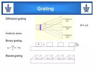
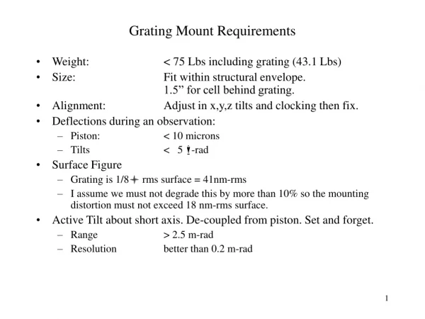
Grating Mount Requirements • Weight: < 75 Lbs including grating (43.1 Lbs) • Size: Fit within structural envelope. 1.5” for cell behind grating. • Alignment: Adjust in x,y,z tilts and clocking then fix. • Deflections during an observation: • Piston: < 10 microns • Tilts < 5 -rad • Surface Figure • Grating is 1/8 rms surface = 41nm-rms • I assume we must not degrade this by more than 10% so the mounting distortion must not exceed 18 nm-rms surface. • Active Tilt about short axis. De-coupled from piston. Set and forget. • Range > 2.5 m-rad • Resolution better than 0.2 m-rad
Grating Mount Requirements, Cont. • Handling and Installation: • Shipping clamps if required for 5 g load. • Set down pads in cell. • Lifting provisions (threaded fittings for eyebolts). • Safety Features: • Cover • Safety Clips • Break-aways on flex rods. • Metrology Provisions: • At least 6 gage points must be provided to locate the grating relative to the cell.
Cell Details Safety Clip Set down pad Tilt flexure Axial support rod with piston/tilt adjustment and compression break-away
Handling pad Lateral locating rod with tension/compression break-aways. Adjustable in length for X-Y position and clocking. Y rod Due to frame interference will have to relocate X lateral to other side, Y rod on this end must be shortened. X rod Handling pad
Tilt Drive Mechanism Stepper motor: 400 steps/rev With 10:1 reducer: 4000 steps/cam rev = 79 -in/step = 6 -rad/step Possible encoder 7 arc-min resolver gives 0.17 m-rad accuracy Mechanical repeatability ~ 20 -rad Cam Follower, Crowned Cam, 0.05” eccentric Preload spring, 30 Lbs
Gage Port Locations Gage Ports Axial Gage Ports Axial Gage Port Gage Ports Gage Port (this one lost to interference)
Axial Gage Port Locations Gage Port
Cell Envelope Problems Interference (cell wall will be adjusted) Apparent interference with mounting platform (platform includes 1.5” cell allowance)
Cell Envelope Violations Note protrusion Another view of the truss tube interference Note protrusion
Cell Envelope Violations Axial Support Encroachment Grating platform envelope includes 1.5” of cell thickness allowance
Cell Envelope Violations No Interference Here
Second Model of Grating Cell • Uses solid elements for cores • Cell mounting flexures modeledwith displacement constraints. • Weight of model (incl 20%) is35.6 Lbs not including drive (10 lbs at 120%) or grating(41.6 Lbs).
Cell Deflection Results Requirements are: In a one hour observation: Piston < 10 microns Tilts about X and Y < 5 -rad
Cell Mounting, Flexure • EDM’d flexure provides high stiffness in 5 directions. • Flexures are 0.040” thick • Force required for 2.5 m-rad rotation is 14 lbs (at 9.5”). Flexure is 1.3” x 3.0”
Cell Mass Properties • Cell Structure (incl 20% contingency) = 36 Lbs • Drive mechanism (incl 20 % contingency) 10 Lbs Total 46 Lbs
Acceleration Vector Change in One Hour • Elevation axis rotation directly effects the instrument. • Azimuth rotation has no effect on the instrument. • Derotator motion rotates the instrument relative to the lateral gravity component. • Derotator rates are similar to azimuth rates. • High derotator rates occur near zenith pointing when the lateral gravity component is small. • Gravity components have been calculated using a spreadsheet. Results are summarized on the following slides. • Lateral g’s change by no more than 0.25 g’s in an hour (peak rate is about 0.63 g’s/hr for a small fraction of an hour). • G’s along the LOS change no more than 0.22 g’s in an hour.
Maximum Gravity Vector Change in One HourResults over 24 hours for one particular target star. Observatory Latitude=32°, Target Star is at 25°
Gravity Vector Components, Change in One Hour Observatory Latitude=32°, Target Star is at 25° Optical axis is acceleration along the line of sight (LOS). Lateral is any direction orthogonal to the LOS.
Maximum Gravity Vector Changes in One Hour, Different Star Locations (The Observatory is at 32 deg Latitude) Note that high derotator rates coincide with high azimuth rates as the LOS passes near zenith but at this time the lateral gravity vector is small. The bump in lateral g’s at 32 degrees may be the result of averaging maximum g’s.
Grating Mounting • Requirements: • < 18 nm-rms surface distortion • small tilts (~ 1 -rad) • small piston (~ 1 -m) • Achieved: • 7.1 nm-rms surface • 0.7 -rad tilt/g …. 0.35 -rad over 30 • 2.6 -m piston/g …. 1.3 -m over 30
MAESTRO Grating, Best Location for Axial Supports 1 g Sag, 5.73 nm-rms (7.06 nm-rms with mounting errors) Supported at X = 4.48”
MAESTRO Grating, Sub-optimal Axial Support Location 1 g Sag, 9.85 nm-rms surface Supported on 3232,3069 and 3419 (X =4.135”)
MAESTRO Grating , Sub-optimal Axial Support Location 1 g Sag, 9.3 nm-rms surface Supported on 3231,3070 and 3420 (X= 4.824”)
Analysis results. Piston and tilts removed. Power left in. X=4.824 indicates the axialsupports are 4.824” from theC/L. Tilts. 0.41 -rad for 1 g Z. <0.07 -rad for X&Y. Axial flex rods will add0.5 -rad tilt. net tilt = 0.65 -rad Grating Distortion, Unit Load Cases, Nm-rms Surface
Grating Tilt Due To Mounting Compliance • Using three identical flex rods tilt is ~ 10 -rad (1 g Z) • Tilt is reduced by: • Doubling the stiffness of the 2xForce rod • Error forces increase from to (V,M) =(.18,.284) to (V,M = (.286,.530) • Small effect on overall performance (7.06 nm-rms to 7.15 nm-rms) • An option is to equalize the load on each axial support • Gravity distortion increases from 5.7 to nm-rms to 8.51 nm-rms • Tilt (surface fit) increases from 0.41 to 0.53 -rad Deformed shape with equally loaded axial rods.
Error Analysis, Gravity and Support Errors, Flex Rod Support • Results arenm-rms surface
Flex Rod Design and Error Force Estimation • Axial flexure. • The single flexure has double the stiffness (details TBD). • Lateral flexures are similar but 6” long with 0.030” thick flexures. Mounting Displacements Piston: 2.6 -m/g Tilt: 0 (nominal) 0.5 -rad max
Flex Rod Error Forces • Use FLEXROD analysis program. • Installed alignment errors will not exceed: • 0.020” of end to end position error and rod straightness error. • 0.5 deg of rod end bend and cell/mirror tilt. • Axial force in rods is less than 21.2 lbs except X rod is 42.4 lbs. • Estimated error forces are listed on slide 6.
Grating Mount Performance • Weight: < 75 Lbs including grating (43.1 Lbs)Achieved: 46+43.1 =90 Lbs (15 Lbs high). • Size: Fit within structural envelope. 1.5” for cell behind grating.Achieved: Still need to fix a minor interference with the prism. • Alignment: Adjust in x,y,z tilts and clocking then fix.Achieved: Adjust x,y and clocking then fix. Fine tune piston and tilts by adjusting grating supports (to cell) … ± 0.020” or ± 4 m-rad range. • Deflections during an observation: • Piston: < 10 microns • Tilts < 5 -radAchieved: 12.5 microns piston 4.3 -rad tilt
Grating Mount Performance • Surface Figure: • Grating is 1/8 rms surface = 41nm-rms • I assume we must not degrade this by more than 10% so the mounting distortion must not exceed 18 nm-rms surface.Achieved: 7.1 nm-rms surface • Active Tilt about short axis. De-coupled from piston. Set and forget. • Range > 2.5 m-rad • Resolution better than 0.2 m-radAchieved: ~ ±5 m-rad range Resolution ~ 6 -rad/step Encoding accuracy ~ 0.17 m-rad using a 7 arc-min resolver on the cam shaft. Could achieve 20 -rad accuracy with a better (more expensive) encoder. Note: With a simple eccentric cam, cam angle and grating tilt are related through the sine of the cam shaft angle. If a linear function is desired the cam could be cut with a linear rise.
Grating Mount Requirements, Cont. • Handling and Installation: • Shipping clamps if required for 5 g load. • Set down pads in cell. • Lifting provisions (threaded fittings for eyebolts). • Achieved: • Shipping clamps: • 8 built in, replace safety clips with 4 additional restraintsload capacity TBD, estimated to be 20 g’s • Set down pads • 3 of the restraints usable for axial set down pads5 pads in the X-Y directions serve as push pulls for X, Y, Rz • Lifting provisions (not shown): • Could replace the 4 safety clips with plates threaded for eye-bolts or could add ¼ threads to upper surface corners.
Grating Mount Requirements, Cont. • Safety Features: • Cover • Safety Clips • Break-aways on flex rods. • Achieved: • Cover, Not Shown, would attach to raised flange (possible clearance issue with prism) • Safety clips provided. • Tension/compression breakaways on lateral rods, compression only on axial rods. • Metrology Provisions: • At least 6 gage points must be provided to locate the grating relative to the cell. • Achieved: 7
Grating Mount Requirements • Weight: < 75 Lbs including grating (43.1 Lbs) • Size: Fit within structural envelope. 1.5” for cell behind grating. • Alignment: Adjust in x,y,z tilts and clocking then fix. • Deflections during an observation: • Piston: < 10 microns • Tilts < 5 -rad • Surface Figure • Grating is 1/8 rms surface = 41nm-rms • I assume we must not degrade this by more than 10% so the mounting distortion must not exceed 18 nm-rms surface. • Active Tilt about short axis. De-coupled from piston. Set and forget. • Range > 2.5 m-rad • Resolution better than 0.2 m-rad