Download
1 / 5
60 likes | 123 Views
Learn about the dispersal of spectral lines by diffraction, dependence on order and grating density, and advantages of concave grating in eliminating chromatic aberration.

E N D
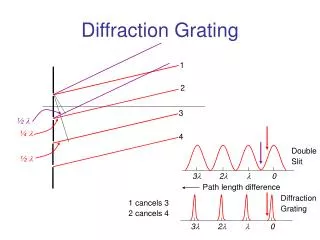
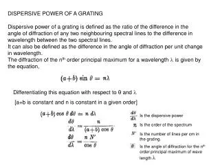
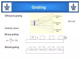
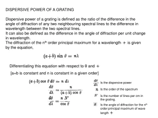
DISPERSIVE POWER OF A GRATING Dispersive power of a grating is defined as the ratio of the difference in the angle of diffraction of any two neighbouring spectral lines to the difference in wavelength between the two spectral lines. It can also be defined as the difference in the angle of diffraction per unit change in wavelength. The diffraction of the nth order principal maximum for a wavelength is given by the equation, Differentiating this equation with respect to θ and [a+b is constant and n is constant in a given order] Is the dispersive power Is the order of the spectrum Is the number of lines per cm in the grating. Is the angle of diffraction for the nth order principal maximum of wave length
It is clear from the above, that the dispersive power of the grating is • directly proportional to the order of the spectrum, • (2) directly proportional to the number of lines per cm and • (3) inversely proportional to cosθ. • Thus, the angular spacing of any two spectral lines is double in the second order spectrum in comparison to the first order. • Secondly, the angular dispersion of the lines is more with a grating having larger number of lines per cm. • Thirdly, the angular dispersion is minimum when θ = 0. If the value of θ is not large the value of cosθ can be taken as unity approximately and the influence of the factor cosθ in the equation can be neglected. • Neglecting the influence of cosθ, it is clear that the angular dispersion of any two spectral lines (in a particular order) is directly proportional to the difference in wavelength between the two spectral lines. A spectrum of this type is called a normal spectrum.
If the linear spacing of two spectral lines of wavelengths in the focal plane of the telescope objective or the photographic plate, then Where is the focal length of the objective The linear dispersion or
CONCAVE REFLECTING GRATING : Use of a plane transmission grating requires two lenses, viz., the collimating lens and the telescope objective. The collimating lens gives a parallel beam of light incident on the grating surface and the telescope objective focuses the diffracted beam. The use of these two lenses if they are not perfectly achromatic, make the spectrum more complex due to chromatic aberration present in the lenses. Rowland developed the concave reflection grating, the use of which eliminates the use of both the lenses. The rulings are made on a concave reflecting surface instead of a plane surface. The concave mirror is a highly polished metal surface and it will diffract the incident beam and also focuses it at the same time. In a concave reflection grating, the effect of chromatic aberration is completely eliminated and it can be conveniently used in those regions of the spectrum for which the glass lenses are not transparent.
Source of radiation In the Fig. APB is the surface of the concave reflecting grating in which the rulings are perpendicular to the plane of the board. C is the centre of curvature of the surface i.e., CP = R. The dotted circle, called the Rowland Circle, has a diameter R. The circle touches the grating surface at P. Spectral image of slit Concave Grating Rowland Circle If a source of light S is placed at any point on the circumference of the Rowland circle PSCI, the dispersed spectral images of the slit are obtained at points such as I on the circumference of the same circle. By keeping the source of light at C, the spectra can be observed at other points on the circumference of the circle.