Download
1 / 21
231 likes | 575 Views
Astronomical Spectroscopy Notes from Richard Gray, Appalachian State, and D. J. Schroeder 1974 in “Methods of Experimental Physics, Vol. 12-Part A Optical and Infrared”, p.463. See also Chapter 3 in “Stellar Photospheres” textbook. Elements Resolution Grating Equation Designs.

E N D
Astronomical SpectroscopyNotes from Richard Gray, Appalachian State, andD. J. Schroeder 1974 in “Methods of Experimental Physics, Vol. 12-Part A Optical and Infrared”, p.463.See also Chapter 3 in “Stellar Photospheres” textbook ElementsResolutionGrating EquationDesigns
Schematic Spectrograph Camera Collimator Detector (CCD) Slit Converging light from telescope Disperser (prism or grating)
Slit Spectrographs • Entrance Aperture: A slit, usually smaller than that of the seeing disk • Collimator: converts a diverging beam to a parallel beam • Dispersing Element: sends light of different colors into different directions • Camera: converts a parallel beam into a converging beam • Detector: CCD, IR array, photographic plate, etc.
Why use a slit? • A slit fixes the resolution, so that it does • not depend on the seeing. • A slit helps to exclude other objects in • the field of view A spectrograph should be designed so that the slit width is approximately the same as the average seeing. Otherwise you will lose a lot of light.
Design Considerations: Resolution vs Throughput Without the disperser, the spectrograph optics would simply reimage the slit on the detector. With the disperser, monochromatic light passing through the spectrograph would result in a single slit image on the detector; its position on the detector is determined by the wavelength of the light. This implies a spectrum is made up of overlapping images of the slit. A wide slit lets in a lot of light, but results in poor resolution. A narrow slit lets in limited light, but results in better resolution.
Design Considerations: Projected slit width f2 f3 Collimator focal length Camera focal length Let s = slit width, p = projected slit width (width of slit on detector). Then, to first order: Optimally, p should have a width equal to two pixels on the detector.Resolution element Δλ = wavelength span associated with p.
Design Considerations: Spectral Resolution vs. Spectral Range
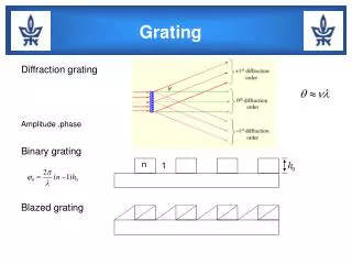
Dispersers Prisms: disperse light into a spectrum because the index of refraction is a function of the wavelength. Usually: n(blue) > n(red). Diffraction gratings: work through the interference of light. Most modern spectrographs use diffraction gratings. Most astronomical spectrographs use reflection gratings instead of transmission gratings. A combination of the two is called a Grism.
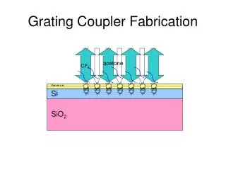
Diffraction Gratings Diffraction gratings are made up of very narrow grooves which have widths comparable to a wavelength of light. For instance,a 1200g/mm grating has spacings in which the groove width is about 833nm. The wavelength of red light is about 650nm. Light reflecting off these grooves will interfere. This leads to dispersion.
The Grating Equation Light reflecting from grooves A and B will interfere constructively if the difference in path length is an integer number of wavelengths. The path length difference will be a + b, where a = d sinα and b = d sinβ. Thus, the two reflected rays will interfere constructively if: d
Meaning: Let m = 1. If a ray of light of wavelength λ strikes a grating of groove spacing d at an angle α with the grating Normal, it will be diffracted at an angle β from the grating. If m, d and α are kept constant, λ is clearly a function of β. Thus, we have dispersion.
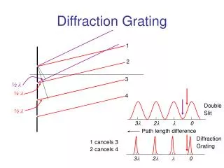
m is called the order of the spectrum. Thus, diffraction gratings produce multiple spectra. If m = 0, we have the zeroth order, undispersed image of the slit. If m = 1, we have two first order spectra on either side of the m = 0 image, etc. Diffraction grating illustrated is a transmission grating. These orders will overlap, which produces problems for grating spectrographs.
Overlapping of Orders If, for instance, you want to observe at 8000Å in 1st order, you will have to deal with the 4000Å light in the 2nd order. This is done either with blocking filters or with cross dispersion. Massey & Hanson 2011arXiv 1010.5270v2.pdf Overlap equation: Meaning that a wavelength of λm in the mth order overlaps with a wavelength of λm+1 in the m+1th order.
Dispersion & Resolution Dispersion is the degree to which the spectrum is spread out. To get high resolution, it is really necessary to use a diffraction grating that has high dispersion. Dispersion (dβ/dλ) is given by: Thus, to get high resolution, three strategies are possible: long camera focal length (f3), high order (m), or small grating spacing (d). The last has some limitations. The first two lead to the two basic designs for high-resolution spectrographs: coudé (long f3) and echelle (high m).
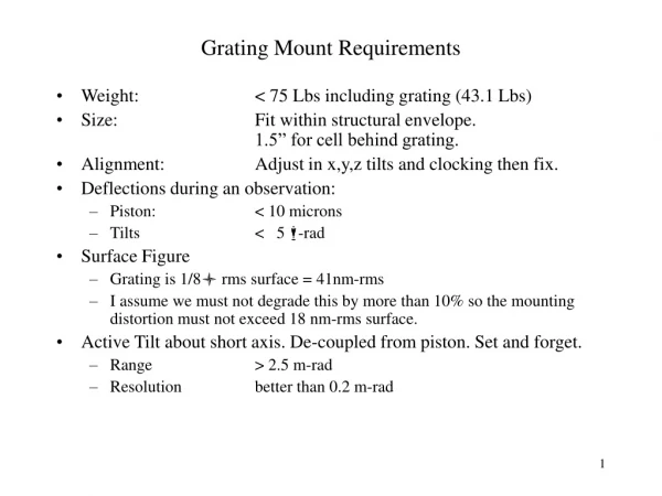
Grating Spectrographs • Reciprocal dispersion P=(d cosβ)/(mf3) (often quoted in units of Å/mm) • Free spectral range m(λ+Δλ)=(m+1)λ Δλ=λ/mλ difference between two orders at same β • Blaze angle with max. intensity whereangle of incidence = angle of reflection
Blaze wavelength • β – θB = θB – α • θB = (α+β)/2δ/2 = (β-α)/2 • Insert in grating eq.λB=2d sinθB cos(δ/2) • Blaze λ in other ordersλm = λB /m • Manufacturers giveθB for α=β (Littrow)
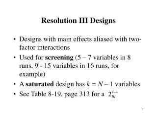
Three basic optical designs for spectrographs Littrow (not commonly used in astronomy). Ebert: used in astronomy, but p = s. Note camera = collimator. Czerny-Turner: most versatile design. Most commonly used in astronomy.
High-resolution spectrographs: Echelle Echelle grating: coarse grating (big d) used at high orders (m ~ 100; tan θB = 2). Kitt Peak 4-m Echelle Orders are separated by cross dispersion: using a second disperser to disperse λ in a direction perpendicular to the echelle dispersion.
Hamilton echelle spectrum format:Vogt 1987, PASP, 99, 1214 m λ