Download
1 / 6
60 likes | 164 Views
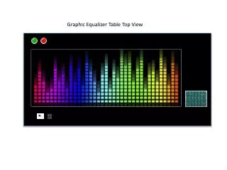
This innovative table features LED display columns for music frequency visualization, proximity sensor for sleep mode activation, and audio hookups for microphone and AUX input. The table's indicators show on/off status and sleep mode. Controlled by microcontroller for Fourier calculations.

E N D
On and Sleep Mode Indicator On Indicator Sleep Indicator The green light indicates when the table is currently on and in use. The red light indicates when the table is currently in sleep mode and not in use, but the table is still on.
Audio Hook ups AUX hookup Microphone There will be two types of functions the display music. A Microphone that will catch any sound made around the table AUX that will display
Proximity Sensor There will also be a proximity sensing section on the table that turns the table on and into sleep mode. The table will automatically be in sleep mode when the table is on, but when you wave your hand over the proximity sensor the table will than get out of sleep mode. This will turn the green light on in the top corner. Another Indicator that the table is on will be a flash of the table when the table turns from Sleep mode to on. In order to turn the table back to sleep mode the user will wave hand over proximity sensor.
LED Displaying section The Main section will consist of 12 LED high by 31 LED wide. Each column will display a certain range of frequencies. As the frequency increases in sound so will the number of LEDS lighting up in each column.
Audio input Microchip/Fourier Calculations Circuit Board Display AD converter The Audio device, microphone or AUX hookup, and the AD converter will both be connected to the microcontroller, Audrino Uno, of which all the Fourier calculations will be done. Then the microcontroller will be connected to a circuit board. The circuit board will be connected to all the Leds, the display.