Download
1 / 13
140 likes | 319 Views
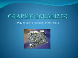
Microcomputer Systems I Final Project. 6 Band Graphic Equalizer. Ryan Boleman Paul Christian Stumpf. Abstract. Our goal with this project was to make a functioning six band equalizer.

E N D
Microcomputer Systems I Final Project 6 Band Graphic Equalizer Ryan Boleman Paul Christian Stumpf
Abstract Our goal with this project was to make a functioning six band equalizer. In this project, each band corresponds to an LED on the board, each band has an adjustable gain, and the final overall signal has a gain, or volume, control.
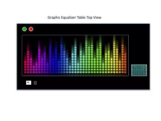
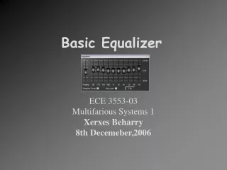
Graphic Equalizer To the left is a picture of a traditional equalizer, which gains each frequency range. Using digital signal processing will implement the same features with much less hardware.
Equalizer • Our equalizer follows the implementations of the block diagram below. 2nd Order IIR Band 1 Filter x[n] g2 gMaster 2nd Order IIR Band 2 Filter gi y[n] 2nd Order IIR Band i Filter gN 2nd Order IIR Band N Filter Diagram by: Dr. Kepuska
Using Lab 4 We first attempted using the FIR filters in fract16 representation, although the code would not work. We used the IIR filters like those used in Lab 4.
Getting the LEDS to match the Band switch (equalizer) //Turns on the LEDs based on number times pressed { case 1: LED=0x01; break; case 2: LED=0x02; break; Etc……default: break; } *pFIO_FLAG_C = 0x0200;
Outputting the Bands Together • One of our biggest hurdles was figuring out how to output all the bands together. • We found that summing the outputs together was the correct way to overcome this. void equalizer_data(void) { low_low_filter(); low_mid_filter(); mid_low_filter(); mid_high_filter(); high_mid_filter(); high_high_filter(); output = ((lowlowLeftOut*lowlow)/8) + ((lowmidLeftOut*lowmid)/8) + ((midlowLeftOut*midlow)/8) + ((midhighLeftOut*midhigh)/8) + ((highmidLeftOut*highmid)/8) + ((highhighLeftOut*highhigh)/8);
Creating a Filter //Low Pass Filter IIR coeficients A and B arrays float llA0[7] = { 1, 1, 1, 1, 1, 1, 1}; float llA1[7] = {0,-1.980438600406, 0, -1.93744503592, 0, -1.884640566237, 0}; float llA2[7] = {0, 0.9826303920074, 0, 0.9402067130157, 0, 0.8884134509986, 0}; float llB0[7] = { 0.477593008357, 1, 0.3228087879648, 1, 0.05990065744308, 1, 1}; float llB1[7] = {0, -1.995410754422, 0, -1.991444851569, 0, -1.937014301303, 0}; float llB2[7] = {0, 1, 0, 1, 0, 1, 0}; We used floating point representation for our coefficients which were obtained using the MATLAB fdatool.
MATLAB fdatool In MATLAB fdatool we created the filters using IIR chebyshev type 2 filters. Chebyshev type 2 seemed to produce the most efficient filter.
Raising the volume without clipping • We had to implement volume adjust without creating a values too large creating clipping. if(*pFIO_FLAG_C == 0x0400) //flag for pf10 { if(volume == 1) { if (volumeadjust<4) { volumeadjust = volumeadjust + 0.1; }
Volume Control Function void volume_data(void) { float gainl = (float) (iChannel0LeftIn<<8); float gainr = (float) (iChannel0RightIn<<8); gainl = gainl * volumeadjust; gainr = gainr * volumeadjust; iChannel0LeftOut = ((int) (gainl))>>8 ; iChannel0RightOut = ((int) (gainr))>>8 ; } This is where the volumeadjust is used to affect the output gain of the input audio.
Possible improvements • Different filter coefficients could be used to create a smoother sound coming out of the equalized data. • More buttons and LEDs could make our program more functional and visually stimulating. • Knobs or sliders could be implemented to help the user adjust the levels with ease. • A LCD display could be integrated into the board to create a better visual of the data.