The E80 Wind Tunnel Experiment
The E80 Wind Tunnel Experiment. the experience will blow you away. by Professor Duron Spring 2006. The Experiment. Objectives To familiarize the student with the basic operation and instrumentation of the HMC wind tunnel


The E80 Wind Tunnel Experiment
E N D
Presentation Transcript
The E80 Wind Tunnel Experiment the experience will blow you away by Professor Duron Spring 2006
The Experiment • Objectives • To familiarize the student with the basic operation and instrumentation of the HMC wind tunnel • To examine the lift and drag forces on airfoil shapes in a flow field, and obtain a qualitative relationship between lift and drag coefficients • To understand the significance of the Reynolds Number, and use Reynolds Number matching to utilize the wind tunnel for modeling of a submersible design problem.
How do planes fly? • Airfoils provide lift • But how?
The Bernoulli Effect • The air across the top of an airfoil experiences constricted flow lines and increased air speed relative to the wing. • According to Bernoulli, this results in a decrease in pressure along the top of the airfoil and provides a lift force. • So, lift is produced by a pressure difference across the wing.
Newton’s 3rd Law • Lift results from the angle of attack. • The boundary layer of air on the airfoil and resulting downwash of air behind the airfoil gives the air a downward force. • According to Newton’s 3rd Law, the airfoil experiences a force in the opposite direction lifting the airfoil. • So, lift is produced by a reaction force on a body caused by deflecting a flow of gas.
Bernoulli or Newton for Lift? • Many mis-apply Bernoulli and Newton's equations and over-simplify the description of the problem of aerodynamic lift. • The most popular incorrect theory of lift is known as the "equal transit time" or "longer path" theory. • Wings are designed with the upper surface longer than the lower surface, to generate higher velocities on the upper surface because the molecules of gas on the upper surface have to reach the trailing edge at the same time as the molecules on the lower surface. • The error in this theory involves the specification of the velocity on the upper surface. • In reality, the velocity on the upper surface of a lifting wing is much higher than the velocity which produces an equal transit time.
Actual Lift is Complicated… • For a gas, we have to simultaneously conserve the mass, momentum, and energy in the flow. • Newton's laws of motion are statements concerning the conservation of momentum. • Bernoulli's equation is derived by considering conservation of energy. • The simultaneous conservation of mass, momentum, and energy of a fluid (while neglecting the effects of air viscosity) are described by Euler Equations. • If we include the effects of viscosity, we have the Navier-Stokes Equations.
Lift and Drag • Drag resists the plane’s motion. A plane with lower drag can fly at faster speeds than a higher drag plane with the same power. • Drag is influenced by the fluid’s viscosity or resistance to flow and by pressure differences within the flow field. • Lift and Drag are represented by nondimensional coefficients defined by the ratio of lift or drag force and fluid kinetic energy. • where is the lift or drag force, measured in pounds or Newtons; ρ is the fluid density (in slugs/ft3 or kg/m3), V is the average flow speed (in ft/s or m/s), and A is the area (ft2 or m2) normal to the force: either the projected frontal area in the case of lift or the wing area for drag.
Flow Patterns and Length Effect • Flow patterns are shown on a Joukowsky foil of very great span (length). • At high angles of attack, the boundary layer separates at the leading edge and stalls producing a drop in lift-to-drag ratio. • Flow around a finite length wing is 3-D. The pressures above and below the wing interact with the surrounding air – particularly as you approach the wing tips. • Leads to the concept of induced drag.
Induced Drag • For a lifting wing, the pressure on the top of the wing is lower than the pressure below the wing. Near the wing tips, the air can move from the region of high pressure into the region of low pressure. • Vortices are created at the wing tips. • If the atmosphere has high humidity, you can sometimes see the vortex lines on an airliner during landing as long thin "clouds" leaving the wing tips. • The wing tip vortices produce a down wash of air behind the wing which is very strong near the wing tips and decreases toward the wing root. • The local angle of attack is increased by the induced flow of the down wash, giving an additional, downstream-facing drag force. • This additional force is called induced drag because it faces downstream and has been "induced" by the action of the tip vortices.
Experimental Fluid Dynamics • Osborne Reynolds (University of Manchester, 1883) discovered that, • if the same atmospheric pressure was used for experiments with wind tunnel models as a full-size airplane would encounter under actual conditions, the results would be invalid. • For the results to be valid, • the air density inside the wind tunnel must be increased by the same proportion as the model is smaller than the actual airplane. • Practically, if a model is 1/10th the size of a full size plane, the air density (number of atmospheres) inside the wind tunnel or the flow velocity must be increased by a factor of 10 to get wind tunnel results that are valid in regular atmospheric conditions with a full size plane. • Two similarly shaped but different sized objects would have the same aerodynamics as long as the Reynolds Numbers for the two objects matched.
What is a boundary layer? • Aerodynamic forces depend on the viscosity of the air. As an object moves through the air, air molecules stick to the object’s surface. • A layer of air is created near the surface that is referred to as a boundary layer. This boundary layer, in effect, changes the shape of the object since the flow reacts to the edge of the boundary layer as if it was the physical surface of the object. • It is also possible for the boundary layer to lift off or even separate from the body creating an effective shape much different than the object’s physical shape. • Boundary layers are very important in determining the lift and drag of an object. • To determine and predict these conditions, aerodynamicists rely on wind tunnel testing and very sophisticated computer analyses.
Reynolds Number • The Reynolds Number quantifies the relative significance of inertia (fluid acceleration) and viscous effects (e.g. drag force, or boundary layer thickness around an object). • If a model flow has the same Reynolds Number as the flow it is meant to represent, the flow patterns and quantitative pressures and forces will be equivalent. • Reynolds Number is defined • where are defined as the fluid density, viscosity (a measure of the fluid’s resistance to motion), the average fluid velocity, and some characteristic object length.
A sample calculation – Boeing 747-400 • Assume the following • Maximum speed = 910km/h • Wing Span = 67 m (typ. Area=4600sqft,chord length=21ft) • Air temperature = -40°C • Need to determine properties of air at specified temperature • http://users.wpi.edu/~ierardi/FireTools/air_prop.html • http://www.onlineconversion.com • http://www.engineeringtoolbox.com/24_162.html • (water properties will be needed for your design) • Reynolds Number associated with one wing
Demo • FoilSim
Mach Number • Aerodynamic forces also depend on the compressibility of the air or fluid. • At low speeds (typically below 200 mph), the density of the fluid remains fairly constant. At high speeds, some of the object’s energy compresses the fluid and changes its density and alters the resulting force on the object. • Near and beyond the speed of sound (approximately 700 mph), shock waves are produced affecting both lift and drag on the object. • The important similarity parameter for compressibility is the Mach Number defined as the ratio of the object’s velocity to the speed of sound
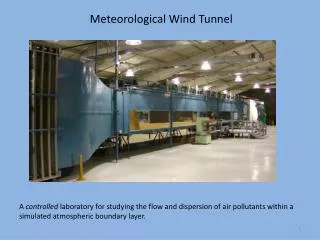
Wind Tunnels (subsonic – less than 250 mph) • Open Circuit Tunnels • the entry and/or exit is open to the lab atmosphere • simple to construct, but use of flow tracers (smoke) is limited • difficult to maintain uniform velocity flow in the test section
Wind Tunnel (cont.) • Close Circuit Tunnels • more uniform flow properties • more challenging to construct and maintain
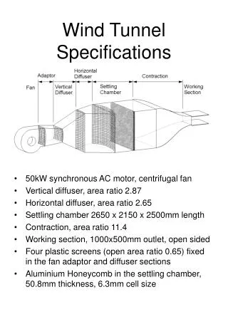
The HMC Wind Tunnel • Designed and constructed by HMC Students and former HMC Professor Jennifer Rossmann. • The wind tunnel is a modified open circuit design with a test section that has a 1’ x 1’ cross section, and can achieve speeds up to 140 mph (Mach 0.2)
Wind Tunnel Instrumentation • A standard pitot probe measures pressure difference. • A stagnation point exists at the nose of the probe where the flow velocity is zero and a small pressure tap measures the pressure at this point. • Flow generally moves around the probe with some average speed and pressure . • A differential manometer measures the difference between the two pressures which varies according to Bernoulli’s equation
Dynamometer • A two component force balance used to measure lift and drag forces. • Forces generated by the model under test cause the deflection of two restrained cantilever beams (along the lift axis and the drag axis). Measurements of the resulting deflections can be used to estimate the applied forces. • Linear Voltage Displacement Transducers (LVDTs) are used to measure the beam displacements.
LVDTs • A typical LVDT consists of a transformer and a moving core. • The transformer consists of 3 symmetrically placed coils inside a cylindrical shield of ferro-magnetic material rendering it impervious to humidity and ordinary magnetic interferences. • The core is made of a nickel-iron alloy and is usually threaded internally to allow attachment to an external actuator (article under test). • Advantages include • Frictionless movement • Long mechanical life • Infinite resolution • Null position stable • Frequency range 50Hz-25kHz
Experiment - Tasks • Pitot probe and velocity calculations • verify fan speed – air velocity relationship • Measure lift and drag forces on an airfoil • determine optimal lift/drag ratio • determine stall angle • confirm experimental results using FoilSim • Determine the airfoil area required to maintain depth for a submersible during operation. • use Reynolds Number to match operating conditions • conduct wind tunnel testing on an airfoil to compute required lift coefficient
Safety • Follow the Dress Code for E80 Lab • Never turn the FAN on without • Making sure the article under test (AUT) is securely fastened inside the test chamber • Checking to see that no loose objects are in the test chamber • Securing the test chamber cover plate • Making sure all test personnel are at a safe distance from the wind tunnel itself (at least 24” in any direction) • Making sure the vent is clear • Do not run the FAN at speeds higher than the posted limit. • Use common sense when working in the wind tunnel facility.
Acknowledgements • Dr. Jennifer Rossmann • Jake Pinheiro • NASA web sites