Download
1 / 44
540 likes | 1.02k Views
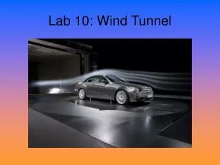
The Wind Tunnel Fluid Measurements. E80 Spring 2014. Overview. Wind Tunnel Introduction Instrumentation Aerodynamic Theory Safety & Operational Issues. Lab Objectives. Safe operation of the wind tunnel Perform basic airspeed measurements & calibrations

E N D
The Wind TunnelFluid Measurements E80 Spring 2014
Overview • Wind Tunnel Introduction • Instrumentation • Aerodynamic Theory • Safety & Operational Issues
Lab Objectives • Safe operation of the wind tunnel • Perform basic airspeed measurements & calibrations • Compare measured lift & drag forces on standard shapes in a flow field • Measure & model drag & lift forces on a rocket body • Calibrate rocket Pitot sensor
Experimental Aerodynamics has a long history… • Aristotle (4th Century BC) writes that air has weight and that bodies moving through fluids are subjected to forces • Archimedes (3rd Century BC) developed theory of hydrostatic pressure
Leonardo da Vinci • Water in a river moves faster where the river is narrow (Bernouli’s theorum) • Observed that the aerodynamic results are the same when a body moves through a fluid as when a fluid moves past a static body at the same velocity—principle used for wind tunnels
Experimental Aerodynamics History • Drag proportional to object’s area (Da Vinci, 15th century • Drag proportional to fluid’s density (Galileo, 17th century) • Drag proportional to velocity squared (Marriotte, 17th century) • Speed of sound in air (Laplace 18th century)
https://www.grc.nasa.gov/www/k-12/airplane/wrights/tunnel.htmlhttps://www.grc.nasa.gov/www/k-12/airplane/wrights/tunnel.html
Wind Tunnel Velocity Range • 27 mph (Wright Flyer) – 25,000 mph (Apollo re-entry)
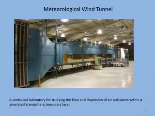
Wind Tunnels (subsonic – less than 250 mph) • Open Circuit Tunnels • the entry and/or exit is open to the lab atmosphere • simple to construct, but use of flow tracers (smoke) is limited • difficult to maintain uniform velocity flow in the test section
Wind Tunnel (cont.) • Close Circuit Tunnels • more uniform flow properties • more challenging to construct and maintain
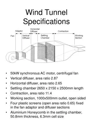
The HMC Wind Tunnel • Designed and constructed by HMC Students and former HMC Professor Jennifer Rossmann. • The wind tunnel is a modified open circuit design with a test section that has a 1’ x 1’ cross section, and can achieve speeds up to 140 mph (Mach 0.2)
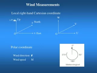
Bernoulli’s Equationconservation of energy applied to flowing fluids.
Pitot Static Tube = static pressure + dynamic pressure
A differential manometer measures the difference between the two pressures which varies according to Bernoulli’s equation
Now that we have something in the wind tunnel… • What aerodynamic forces do we want to measure? • Lift & Drag
Aerodynamic ForcesWhat force does a moving fluid exert on a solid body immersed in the fluid?
Bernoulli’s Principle Applied to a Standard Shape (airfoil) Streamlines Flow over upper curved surface is faster and the Bernoulli effect results in lower pressure over the top surface
Lift & Drag • Integrate pressure and shear stress distributions around body surface to get resultant force • Resolve the resultant force into two perpendicular forces: • Lift: component of resultant force perpendicular to velocity vector (free stream). • Drag: The component of resultant force parallel to the incoming velocity vector.
Forces on a Rocket www.grc.nasa.gov/WWW/K-12/rocket/rktfor.html Differences between a Rocket & Airplane? • Where do the following forces act through? • Lift • Drag • Weight • Thrust
Back to aerodynamic forces… Lift & drag forces are typically found experimentally rather than integrating pressure & shear stress…
Drag & Lift Equations Define: (attributed to Lord Rayleigh) • FD is the drag force (force in direction of flow) • FL is the lift force (perpendicular to direction of flow) • r is the mass density of the fluid • n is the speed of the fluid • A is the reference Area • CD is the coefficient of drag • CL is the coefficient of Lift
Coefficients of Drag & Lift Rearranging: Ratio of lift or drag force to fluid kinetic energy Determined experimentally in the wind tunnel
Experimental Fluid Dynamics • Osborne Reynolds (University of Manchester, 1883) discovered that, • if the same atmospheric pressure was used for experiments with wind tunnel models as a full-size airplane would encounter under actual conditions, the results would be invalid. • For the results to be valid, • the air density inside the wind tunnel must be increased by the same proportion as the model is smaller than the actual airplane. • Practically, if a model is 1/10th the size of a full size plane, the air density (number of atmospheres) inside the wind tunnel or the flow velocity must be increased by a factor of 10 to get wind tunnel results that are valid in regular atmospheric conditions with a full size plane. • Two similarly shaped but different sized objects would have the same aerodynamics as long as the Reynolds Numbers for the two objects matched.
Reynolds Number (Re) • The Reynolds Number is a dimensionless number that quantifies the relative significance of inertia (fluid acceleration) and viscous effects (e.g. drag force, or boundary layer thickness around an object). • If a model flow has the same Reynolds Number as the flow it is meant to represent, the flow patterns and quantitative pressures and forces will be equivalent. • Reynolds Number is defined • where are defined as the fluid density, viscosity (a measure of the fluid’s resistance to motion), the average fluid velocity, and some characteristic object length.
Mach Number • Aerodynamic forces also depend on the compressibility of the air or fluid. • At low speeds (typically below 200 mph), the density of the fluid remains fairly constant. At high speeds, some of the object’s energy compresses the fluid and changes its density and alters the resulting force on the object. • Near and beyond the speed of sound (approximately 700 mph), shock waves are produced affecting both lift and drag on the object. • The important similarity parameter for compressibility is the Mach Number defined as the ratio of the object’s velocity to the speed of sound
Newton’s Hypothesis “Pressure” Drag
What is a boundary layer? • Aerodynamic forces depend on the viscosity of the air. As an object moves through the air, air molecules stick to the object’s surface. • A layer of air is created near the surface that is referred to as a boundary layer. This boundary layer, in effect, changes the shape of the object since the flow reacts to the edge of the boundary layer as if it was the physical surface of the object. • It is also possible for the boundary layer to lift off or even separate from the body creating an effective shape much different than the object’s physical shape. • Boundary layers are very important in determining the lift and drag of an object. • To determine and predict these conditions, aerodynamicists rely on wind tunnel testing and very sophisticated computer analyses.
Viscous Boundary Layer “Skin Friction” Drag
Dynamometer • A two component force balance used to measure lift and drag forces. • Forces generated by the model under test cause the deflection of two restrained cantilever beams (along the lift axis and the drag axis). Measurements of the resulting deflections can be used to estimate the applied forces. • Linear Voltage Displacement Transducers (LVDTs) are used to measure the beam displacements.
Low Voltage Displacement Transducers (LVDTs) • Benefits • Frictionless movement • Long mechanical life • Infinite resolution • Null position stable • Frequency range 50Hz-25kHz
CD is not constant… • CD varies with fluid speed, flow direction, object position, object size, fluid density, and fluid viscosity and characteristic length scale… • e.g., cylinder CD = f( fluid velocity v, fluid density r, fluid viscosity m, and cylinder length L) • How many experiments needed? • Lets say we analyzed 10 lengths, and for each of those we analyzed 10 velocities, etc…. requires 10^4 = 10,000 experiments!
Dimensional Analysis • Method to reduce the complexity of variables that affect a physical phenomena. • Any equation must have the same units on left & right sides… • DA gives the number and form of independent dimensionless parameters which govern a physical phenomena.
Dimensional Analysis – Drag on a Sphere • Detailed dimensional analysis for a determining the drag on a sphere is here: R. Subramanian. “Dimensional Analysis – Drag on a Sphere.” http://web2.clarkson.edu/projects/subramanian/ch301/notes/dimensionfluids.pdf • Similarly,
Safety Always be Thinking About Risk Management! • Corporate • Professional • Personal
Safety • Follow the Dress Code for E80 Lab • Never turn the FAN on without • Making sure the article under test (AUT) is securely fastened inside the test chamber • Checking to see that no loose objects are in the test chamber • Securing the test chamber cover plate • Making sure all test personnel are at a safe distance from the wind tunnel itself (at least 24” in any direction) • Making sure the vent is clear • Do not run the FAN at speeds higher than the posted limit. • Use common sense when working in the wind tunnel facility.