Daimler Wind Tunnel Project
Daimler Wind Tunnel Project. Project Review. Capstone Team Andre Nylund Chris Grewell Craig Lechtenberg Fadel Al Jutail Matt Melius Mufeed Yacoub Team Advisor Dr. Raul Bayoán Cal Customer Daimler Trucks North America. Project Review. Tunnel Details 12,000 sq. ft. facility
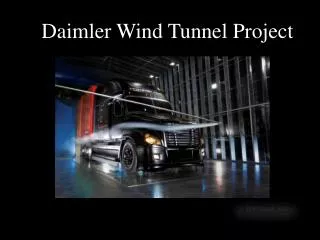

Daimler Wind Tunnel Project
E N D
Presentation Transcript
Project Review • Capstone Team • Andre Nylund • Chris Grewell • Craig Lechtenberg • Fadel Al Jutail • Matt Melius • MufeedYacoub • Team Advisor • Dr. Raul Bayoán Cal • Customer • Daimler Trucks North America
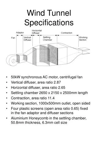
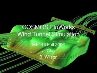
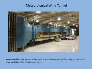
Project Review Tunnel Details • 12,000 sq. ft. facility • Wind speeds up to 65 • 30ft long test section 21ft wide 26ft tall
Project Review • Rotating floor panel to test various angles of attack Tunnel Details • Smoke wand for flow visualization • Pressure sensitive floor for calculating trucks drag coefficient.
Project Review Mission Statement: Improve smoke testing methods • Increase the testable area within the wind tunnel • Increase stability of the system • Deliver smoke to location of interest accurately • Electronically controlled system to eliminate human error • Provide these requirements while maintaining negligible aerodynamic impact to test region • Delivery of final product by June,16th
Mile Stone Progress PDS completion – January 30th • Two axis motion • 20’ Horizontal travel • 17’ Vertical travel • Zero residual impact when not in use • Removes itself form wind tunnel completely when not in use • Aerodynamic Profile External and Internal Search – February 17th
External Search • Typically, traversing systems are used to study the airflow behind a test model (ex. pressure probe is downstream of the test subject) Test Subject Pressure Probe Air Flow
External Search • Traversing systems commonly use linear actuators for precise motion control. • Common Applications • Flow field and wake survey • behind test section • Small test sections • scale models etc.
External Search Roof Mounted Traversing Probe Traversing Volume • 3m x 4m x 6m Positional Accuracy • +/- 1mm
External Search Roof Mounted Traversing Probe • full size automotive wind tunnel • downstream probe Traversing Volume • 5m x 12m x 13m Positional Accuracy • +/- 1.5mm
External Search • Floor mounted track • Singly supported • Range of travel dictated by rail length
External Search Linear Actuators Pre-fabricated Sealed Unit Reliable
External Search • Rail and Linear bearing systems • High precision offers accurate placement of carriage
External Search • Motion Control • Stepper Motor • Servo Motors and Drives • Gear Boxes
Internal Concept: Vertical Floor Rail Z Vertical Rail and Carriage X Smoke wand Wind tunnel wall Horizontal Rails and Carriages Wind Tunnel
Internal Concept: Vertical Floor Rail Horizontal Rail and Carriage Truck profile Wind tunnel wall Wind Tunnel Vertical Rail and Carriage Smoke Wand Z Horizontal Rail and Carriage X
Internal Concept: Cantilever • Possible project scope change Cantilever cable support Wind tunnel wall Vertical Rail and Carriage Horizontal Rail and Carriage Wind Tunnel Z Carbon Fiber Smoke Wand X
Mile Stone Progress PDS completion – January 30th • Two axis motion • 20’ Horizontal travel • 17’ Vertical travel • Zero residual impact when not in use • Removes itself form wind tunnel completely when not in use • Aerodynamic Profile External and Internal Search – February 17th Concept selection – February 22nd • Cantilever Detailed Design– February 22nd to May 18th Fabrication completion – May 31st Product delivery – June 16th
Detailed Design Load Calculations • Gravity on the Horizontal rail • 355N • Gravity on the smoke wand • 107 N • Wind load on the smoke wand • Distributed load of 361N • Moment of 990N*m at wand support rollers • Weight of the entire system Wand Support Rollers Drive Motor Wind Tunnel Wall Vertical Rails Vertical Carriages Wind Tunnel Smoke Wand Z X Horizontal Rail Horizontal Carriage
Detailed Design • Mechanical Component Selection • Horizontal rail and carriage • Vertical rail and carriage • Lifting mechanics • Lifting motors • Structural Design • Vertical rail supports • Baseplate mounting • Structure stabilization
Detailed Design • Control System • Safety • Operational safety • Limit switches • Human interaction • Zero energy state • Vertical motion lockout