Download
1 / 1
10 likes | 145 Views
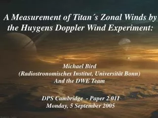
The Huygens Doppler Wind Experiment M.K. Bird 1 , R. Dutta-Roy 1 , M. Allison 2 , S.W. Asmar 3 , D.H. Atkinson 4 , W.M. Folkner 3 , R.A. Preston 3 , G.L. Tyler 5 , L. Iess 6 , P. Edenhofer 7 , D. Plettemeier 8

E N D
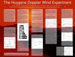
The Huygens Doppler Wind Experiment M.K. Bird 1, R. Dutta-Roy 1, M. Allison 2, S.W. Asmar 3, D.H. Atkinson 4, W.M. Folkner 3, R.A. Preston 3, G.L. Tyler 5, L. Iess 6, P. Edenhofer 7, D. Plettemeier 8 1 Radioastronomisches Institut, Universität Bonn, Auf dem Hügel 71, 53121 Bonn, Germany, 2 NASA-Goddard Institute for Space Studies, New York, NY 10025, USA, 3 Jet Propulsion Laboratory, California Institute of Technology, Pasadena, CA 91109, USA, 4 Department of Electrical Engineering, University of Idaho, Moscow, ID 83843, USA, 5 Center for Radar Astronomy, Stanford University, Stanfort, CA 94305, USA, 6 Dipartimento Aerospaziale, Universitá di Roma ‘La Sapienza‘, 00184 Roma, Italy, 7 Institut für Hochfrequenztechnik, Universität Bochum, 44801 Bochum, Germany, 8 Elektrotechnisches Institut, Technische Universität Dresden, 01062 Dresden, Germany The Wind Retrieval Algorithm Neglecting refractive and relativistic effects on the signal, the Doppler shift is given by where vLS is the speed along the line of sight between Cassini and Huygens. In a Titan centered co-rotating frame, vLS can be written as where vdes is the Huygens descent velocity, vNS is its meridional velocity, vEW is its zonal velocity, vC represents the velocity of Cassini and nLS is a unit vector pointing along the line of sight from Cassini to Huygens. In order to compute the zonal velocity vEW, the equation above may be rearranged to where the angles x denote the angles between the line of sight and the corresponding velocities vx. This equation is used to compute the zonal speed of Huygens. It contains eight parameters, only one of which (vLS) is measured by DWE. The other velocities are provided from various other sources. The angles are computed from the positions of Cassini (provided by JPL) and Huygens. The Huygens altitude profile, as well as the longitude and latitude at the moment of the link acquisition, are computed in an iterative process. The retrieved zonal wind speed may be integrated to obtain the Probe´s longitude. Any meridional motion is neglected to a first approximation (see “Geometry“ and “Error Analysis“). Error Analysis The equation for vEW (see “The Wind Retrieval Algorithm“) contains eight parameters, which have limited accuracy. In order to estimate the impact of the uncertainties of parameters on the wind retrieval process, we computed the error contribution function err(x), which is defined as where x represents all parameters on the right side of the equation for vEW and x is their expected precision. The result of this analysis (1 error contributions) is shown in the following figure on two different scales. The error contribution err(vLS) is the DWE instrumental error: mainly oscillator noise but also a possible systematic bias (see “DWE Hardware“). Whereas the error contributions due to inaccurate velocities are predominantly random, error contributions due to inaccurate angles (positions) are predominantly systematic and correlated. Systematic errors do not affect the shape of the retrieved zonal wind profile, but lead to a systematic offset between the real profile and the retrieved profile. Because the observation geometry improves during the mission, all errors tend to decrease with time. By far the largest error is that from angle C, i.e., the angle between the line of sight and the large Cassini velocity. This error is systematic and may lead to a systematic bias of the retrieved profile. The largest random error contributions are from vdes (where we assume a 1% random error for the descent velocity) and, for times late in the descent, the measurement errors in vLS. These indicate that changes of the zonal wind speed of the order of several cm/s may be observable. At this scale, the figure does not show the effect of an error in NS (latitudinal position), because it is less than 1 cm/s for most of the descent. Simulation Results We constructed simulated data by computing a synthetic Doppler profile and adding to it in-flight checkout data (nominal Doppler shift = 0). The resulting profile was then de-biased and the spurious frequency oscillation was filtered out (see “DWE Hardware“). A Monte Carlo approach was used to account for all systematic and random error contributions. The wind profile derived for the case where the initial Huygens position assumed for the retrieval is identical to the one used for constructing the simulated data (vanishing systematic errors) is shown in the upper panel of the following figure and compared with the input wind profile. The lower panel shows the residuals between the (prograde) zonal wind input profile and the retrieved profile. The merging error envelopes in the upper panel indicate that the systematic errors decrease with time. This is also true if the input profile is retrograde. If the initial Huygens target longitude (assumed for the retrieval) is 50 km east of the actual Probe longitude, one obtains this result: The residuals are obviously larger, but the systematic error in the zonal wind speed decreases with time even in this case. As demonstrated with other cases where the initial target longitude is west of the actual longitude and/or the zonal wind is retrograde (not shown here), the retrieval algorithm is robust in maintaining this self-correcting capability. Introduction A Doppler Wind Experiment (DWE) will be performed during the Titan atmospheric descent of the ESA Huygens Probe on 14 January 2005. The direction and strength of Titan‘s zonal winds will be determined from the start of the mission at an altitude of ~160 km down to the surface. The Probe‘s wind-induced horizontal motion will be derived from the residual Doppler shift of its S-band radio link to the Cassini Orbiter, corrected for all known orbit and propagation effects. A complementary Doppler measurement from Earth will be performed that may enable a seperation of the zonal and meridional wind components. A Titan wind retrieval algorithm has been developed for DWE and has been tested using simulation studies. An extensive error analysis has been performed to identify the sources of the largest random and systematic errors. DWE Hardware Two redundant S-band links (Chain A at 2040 MHz and Chain B at 2098 MHz) will be transmitted from the Huygens Probe to the Cassini Orbiter. Two rubidium-based ultra-stable oscillators (USOs), needed for generating an accurate and stable carrier frequency in the transmitter and measuring it in the receiver, are used in chain A only. DWE relies on accurate knowledge of the absolute value of the Doppler shift induced on the carrier signal by the relative motion between Cassini and Huygens. Instrument checkouts performed regularly every six months during the cruise to Saturn were used to monitor possible instrumental drift of the Doppler shift measurement. Because Huygens is attached to Cassini during cruise, the nominal Doppler shift is zero. The following figure shows the measured carrier Doppler shift fR during all in-flight checkouts performed with the USOs thus far. The individual frequency measurements appear in this plot as a cloud of black dots. The variable thickness of the cloud is caused by the variable amplitude of a spurious oscillation of the USO output frequency. This spurious oscillation, which has a period of 2.7 s, may be filtered out by applying a simple box filter (building a running mean) over one or more frequency oscillation periods. For example, the mean value of the frequency measurements averaged over 2.7 s is shown by the solid white line. Notice that this white line is offset from the nominal 0 Hz and the offset bias is proportional to the oscillation amplitude. We thus use the relation between the oscillation amplitude and the frequency offset to eliminate the bias from the frequency measurement. Meteorology on Titan Titan rotates rather slowly (spin period: 16 Earth days) and has a small but significant temperature difference T between the equator and the poles, which was measured by Voyager 1 during its reconnaissance with Titan in 1980. Due to these two findings, most wind models predict a strong atmospheric superrotation: strong zonal winds in the prograde (westeast) direction and negligible meridional winds. This has been confirmed by recent ground-based measurements. The following figure shows the Titan meteorology as inferred from the Voyager 1 results and a typical zonal wind model. The zonal wind speed is defined positive in the prograde direction. Geometry The observation geometry during the mission, obviously a crucial parameter for DWE as indicated by the many angles in the equation for vEW above, is shown in the following figure. It can be seen that the projection of the zonal velocity onto the line of sight (cos(EW)) increases during the mission. Conversely, the projection of the vertical velocity (cos(des)) decreases. Since the trajectories of both Cassini and Huygens lie near the Titan equator, the angle (NS) is near 90° throughout the Huygens descent. This allows us to neglect possible meridional motions. Even if meridional winds are larger than expected, their contribution to the measured Doppler shift is small. Earth-based Measurements It is planned that similar Doppler measurements will also be performed on Earth. The angular separation of the radio links Huygens-Cassini and Huygens-Earth is not optimal, but the two measurement sets could probably still be used to separate the zonal and meridional winds. Titan ground tracks showing the observation geometry for the Earth-based DWE is shown in the figure to the right: Reference M.K. Bird, R. Dutta-Roy, M. Heyl, M. Allison, S.W. Asmar, W.M. Folkner, R.A. Preston, D.H. Atkinson, P. Edenhofer, D. Plettemeier, R. Wohlmut, L. Iess, G.L. Tyler, The Huygens Doppler Wind Experiment: Titan Winds Derived from Probe Radio Frequency Measurements, Space Sci. Rev.104, 613-640, 2002