Download
1 / 18
180 likes | 206 Views
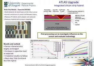
Study of support structure for silicon tracking modules in ATLAS upgrade, focusing on mechanical strength and thermal management. Analysis includes FEA solutions, thermal runaway solutions, efficient support methods, and composite materials selection.

E N D
SLHC Program Review SCIPP May 3, 2007 Mechanical and Thermal Management for ATLAS Upgrade Silicon Tracking System W. O. Miller (iTi) Carl Haber (LBNL), Gil Gilchriese (LBNL)
Inner Detector Support and Cooling • Topics • Support Options for staves at mean radius of: • 380, 490, and 600mm • Based on 10cm wide by 10cm long silicon modules mounted on a stave constructed of composite material with embedded cooling • Composite sandwich concept-embedded cooling tube • Each stave is 1m length • FEA solutions for cylindrical shell geometry, FEA for end plate geometry to be considered next • Gravity sag for shell supporting single layer of staves • Also sag of a shell-like structure supporting two layers of staves (490mm and 600m used as an example) • Thermal Runaway Solutions • For single and Triple U-Tube coolant tube geometry VG 2
10cm Silicon Module Stave FEA Parameters Stave length ~1074mm, overall mass ~0.67kg VG 4
Inner Layers 380R to 600R mm • Comments on Support Structure---2m length • If composed of 1m staves the mass per stave is approximated at 0.67kg per unit • At 600mm mean radius this equates to approximately 51.2kg (estimated to be 38 staves around circumference • If the layers at 490mm are carried by the same structure the mass increases to 94.2kg • Question becomes: What is the most material efficient method of supporting this mass, i.e. minimizing radiation length? • Also, one must consider the potential for supporting additional layers, like for example at 380mm R • Options to be considered: • Three disk pattern with outer and inner shell: outer shell would be conceivably be supported at mid-plane at four corner points • Individual shells for each layer: shell might be single layer facing or composite sandwich • Although single layer is preferred to simplify construction VG 5
Inner Layers 380R to 600R mm (cont.) • If one shell for each layer, then it becomes advisable to use reinforcing rings placed at discrete points in Z • Rings would be used to provide mid-span supports for staves • Ultimately, this likely will permit removing some material from the composite stave structure • What prospect exists for supporting multi-layers of staves with one shell? • Questions become: • What is an appropriate ratio of structure mass to detector elements, aside from zero • What composite material is best suited to construction approach • Shell lay-up; possibly mid-range modulus to avoid fiber fracture, depends on the amount of deformation • Flat panel geometry, can use very high modulus fibers without complications • Large sandwich structures • mass of core may not be insignificant • LBNL approach is look at various options with simple models first VG 6
Example Barrel Structures- Disk Primary • Disk Support Structure • Stave, 1m long supported at ends, hopefully with near “fixed end condition” • Disks are sandwich structure, high modulus composite facings with HC core • Inserts in HC to provide registration points for precision locating pins • Outer and Inner composite shells, single layer (0.5mm) to stabilize disks • Outer shell connects to outermost silicon layers at their “disk planes” of suspension Staves slide in place, retained by plates located with pins VG 7
Example Barrel Structures- Shell Primary • Shell Concept • Potentially supports two stave layers • Locating features in mounting rings are machined in one set-up • Rings are inserted over shell and held in place with alignment fixture during bonding to shell • 1m Stave Assembly • Stave mounts from end, engaging alignment pins in rings • Staves meet at center, locked at this point Locating pins in rings Light weight composite sandwich rings VG 8
Stave Support Concept-10cm Wide Module • Shell Concept: Single layer • Avoid sandwich construction complexity • Shell stiffness enhanced with radial rings • Staves are mounted to rings • Five rings chosen for 2m shell design • Provides a mid-span support for stave • Rings although sandwich members are modeled as single thickness laminate • Concept offers potential for supporting two detector layers Mean shell radius 595cm VG 9
FEA of Support Options- Single Shell Max sag at rings <30microns • Example #1---One Silicon Layer • 0.5mm thick composite, ring reinforced shell, 2m long at radius of 595mm • Rings used as primary support for 1m staves, 38 staves for a total of 76 to make 2m length • Mass of support shell and outer rings 6.64kg • Rings as modeled are 5cm deep, 1mm thick facings • From a practical sense the rings would be constructed as a sandwich, whereas the shell is not • Mass of 76 staves is ~51.15kg • Deflection at highest point of the rings is < 30microns Composite: M55J fiber/cyanate ester resin, 60% fiber fraction ρ=1.64g/cc Shell support: simple constraint, mid-plane at four corners VG 10
FEA of Support Options- Single Shell-Two Layers Max sag at rings <14microns • Example #1---Two Silicon Layers • 0.5mm thick composite, ring reinforced shell, 2m long at radius of 595mm • Added inner rings, 5cm depth, same as outer • Mass of support shell and outer rings 7.98kg • Inner surface has 64 staves to populate 2m, whereas the outer was 76 • Total stave mass ~94.2kg • Deflection at highest point of the rings is < 14microns • Inner rings increased total stiffness significantly • Without inner staves, but with outer staves the deflection is <8 microns Total mass: structure plus staves 102.2kg VG 11
FEA of Support Options- Flat Panel • Example #2-Flat Panel Construction • Flat sandwich panels are bonded together; ring reinforcements are used for stave attachment • Basic concept used in ATLAS pixel detector • Flat panels used 250micron M55J composite facings with a 6.35mm HC core • Panels have cut-outs to reduce mass • This is an area that can be improved • Structure mass=7.65kg, supporting stave mass of 51.2kg Maximum sag of rings where upper and lower stave attach is 19microns Mean structure radius=595mm VG 12
1st Order Summary of Stave Supports • Solution of Disk Support in Process • Requires is little more exact definition of geometry • Want to be careful that structure is not over simplified • Shell design • Looks quite practical structurally • Mounting of staves on external rings looks practical and quite accessible • 1m staves would be fixed at Z=0, allowing free expansion or contraction in both directions • Mounting of staves inside a shell is more difficult • Light weighting cut-outs could provide the necessary access • Again fix the staves at Z=0 • Disk design • Assembly can be tricky, considering stave length and associated services • Stave must pass thru a slot and engage alignment pins at Z=0 • Choice of which end to fix the stave against movement is not clear • Z= 0 might still be a possibility, but is a detail to be resolved VG 13
Thermal Runaway in 10cm Module • Thermal Runaway Issue: Leakage Current Induced • One of geometry, material conductivities, material thickness, etc. • Strongly influenced by span from outermost point on module to point of cooling • Also, affected by heat load from chips imposed on detector Two cooling options for 10cm wide stave model VG 14
Thermal Stability Solutions • Solutions for: • Two geometries • Two leakage current values (conventionally referenced to 0ºC) • Results for stave with embedded cooling tube, single U-Tube or Triple U-Tube • No apparent problem, particularly based on leakage data considered to be most likely to be experienced in SLHC Single U-tube Triple U-Tube VG 15
Thermal Runaway Conclusions • Triple U-Tube • Could use C3F8 with considerable safety margin, head-room 19.6ºC using -25ºC cooling fluid temperature • Single U-Tube • Use of C3F8 at -25ºC a bit more problematic, even still the head-room is 9ºC • In short • If a need exists for uniform module surface temperature at or below -25ºC for reasons other than suppressing leakage problems, then • one should consider the CO2 alternative coolant • -40ºC bulk inlet for the Single U-Tube • -35ºC bulk inlet for the Triple U-Tube VG 16
Stave Summary (Data for 6cm Module) • Description: 1m Stave, K13D2U 4/1 fiber Orientation, 4.6mm core height, graphite fiber HC, semi-flatten Al tube (12mil wall, U-Tube shape), Al end caps, steel pins • Gravity sag (FEA) • Purely horizontal and vertical : 55.5µm and 3.5µm respectively • Thermal • Without leakage current heating: average module -17 to -17.8ºC, electronic chips -15.5ºC with -25ºC coolant • Thermal strain 5µm out-of-plane: 50ºC temperature change plus 0.5W per chip • Thermal strain 6.2µm out-of-plane: 60ºC temperature change only • Coolant Tube Pressure • 4.6mm semi-flat tube: 1.5µm out-of-plane for 100psi (6.9bar C3F8) • For CO2 use small diameter round tube, deflections and stresses become non-issue VG 17
Stave Summary (10cm Module) • Thermal solutions (no structural FEA as yet) • Description: 10 chips 0.5W each, same facings and essentially same hybrid dimensions • Initial question: how to cover wide transverse heated span using same inside HC core height (4.6mm) • Small diameter tube (2.8mm) with POCO Foam saddle to accept heat from facings— effectively removes the heat • 10W per 2.5cm long module: Single U-Tube module surface temp of -14.5ºC and Triple U-Tube is -17ºC • 10W per 2.5cm long module: Thermal runaway not a problem in either case, 9ºC “head-room” for Single U-Tube and 19ºC for Triple U-Tube • More work needed for 10cm wide stave design • If CO2, then current tube and saddle design OK, if C3F8 then re-visit tube size (reduce thickness of saddle slightly) • Look into thermal strains and gravity sag- do not anticipate problems VG 18