Download
1 / 22
220 likes | 349 Views
DSP handling of Video sources and Etherenet data flow. Technion – Israel Institute of Technology High speed Digital Lab. Supervisor : Moni Orbach Students : Reuven Yogev Raviv Zehurai. Project D1722 Final Presentation 24.08.04. Evaluation Board. Memories. 00100. FIFO. Bridging

E N D
DSP handling of Video sources and Etherenet data flow Technion – Israel Institute of Technology High speed Digital Lab Supervisor: Moni Orbach Students: Reuven Yogev Raviv Zehurai Project D1722 Final Presentation 24.08.04
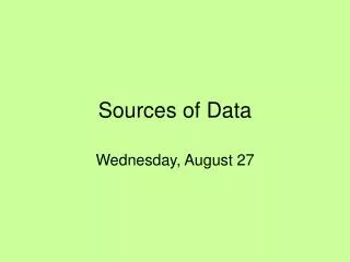
Evaluation Board Memories 00100 FIFO Bridging Card DSP 00100 10100 00011 Video Sources 00100 Ethernet Controller System Structure
Hardware Integration – step A The first stage was to connect the video camera to the bridging card, in order to examine the camera’s operation and our abilities to initialize it.
Hardware Integration – step A We received the information from the video camera through connector C2 along with the relevant control signals (as programmed in VHDL). We used Logic Analyzer to view the signals. This information is later on inserted to the FIFO on the evaluation board.
0xFFFFFFFF FIFO 0x00000000 0xFFFF0000 0x0000FFFF Hardware Integration – step B The second step was to connect the bridging card to the evaluation board. We disconnected the camera video from the bridging card and it injected Test Pattern to the FIFO, accompanied by appropriate control signals.
Hardware Integration – step B The DSP was unable to read the FIFO, because it was burned, therefore we were instructed to move on. We reduced the signal to a third of its value on the entrance to the FIFO.
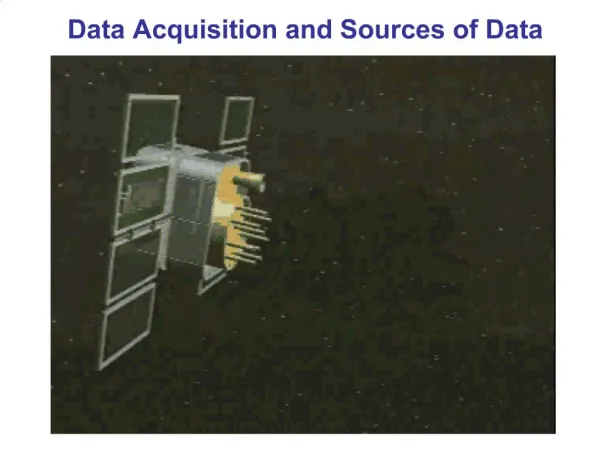
The C6416 DSP System block diagram
The main components of the DSP • The main core of the system – CPU • L1 Program memory – 16KB • L1 Data memory – 16KB • The Enhanced DMA • L2 memory / cache – 1MB • EMIF A (64 bit) and EMIF B (16 bit) • McBSP • Timers
The EDMA Architecture • The EDMA controls access to resources and arbitrates between concurrent transfers. • The EDMA includes 64 channels with programmable priority, and has the ability to link and chain data transfers. • Transfer requests originate from many requestors: the sixty-four programmable EDMA channels, the level 2 (L2) memory controller, and other master peripherals.
SUBMITTING TRANSFER REQUEST The transfer request chain
Assuming each makes a submission on the same cycle, the requestor closest to the TC arrives first, and the farthest arrives last. • Once a request is within the request chain, it has priority over new submissions, such that the requests at the end of the chain (HPI/PCI) do not get starved for servicing. • Once a transfer request reaches the end of the request chain, it is sent to the transfer crossbar (TC). Within TC, the transfer request shifts into one of the transfer request queues to await processing. • Once the transfer request reaches the head of its queue, it is submitted to the address generation/transfer logic for processing. The address generation/transfer logic only services one transfer request from each queue. • In order to maximize the data transfer bandwidth in a system, we should utilize all queues.
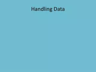
The EDMA Controller Architecture The EDMA controller block diagram
The EDMA controller comprises: • Event and interrupt processing registers • Event encoder • Parameter RAM (PaRAM) • Address generation hardware
The Mechanism of Data Transfer The event register captures EDMA events. An event is a synchronization signal that triggers an EDMA channel to start a transfer. If events occur simultaneously, the event encoder resolves them. The transfer parameters corresponding to this event are stored in the EDMA parameter RAM, and are passed onto the address generation hardware, which address the EMIF and/or peripherals to perform the necessary read and write transactions.
The Parameter Ram (PaRAM) • The table is a 2K-byte block of internal parameter RAM. • The PaRAM table consists of six-word parameter entries of 24 bytes each, for a total of 85 entries. • The contents of the 2K-byte PaRAM include 64 transfer parameter entries for the 64 EDMA events. • Remaining parameter entries (21 entries) serve as additional parameter sets used for linking transfers. • Once an event is captured, its parameter entries are read from one of the top 64 entries in the PaRAM. These parameter entries are then sent to the address generation hardware.
The Structure of EDMA channel parameter entry Each parameter entry of an EDMA event is organized into six 32-bit words or 24 bytes
EDMA Channel Options Parameter (OPT) EDMA Channel Source Address Parameter (SRC)
EDMA Channel Transfer Count Parameter (CNT) EDMA Channel Destination Address Parameter (DST)
EDMA Channel Index Parameter (IDX) EDMA Channel Count Reload/Link Address Parameter (RLD)
The Link Feature An important capability of the EDMA is that of linking. By providing a link address and setting LINK = 1 in the transfer options, an EDMA channel loads a new entry from PaRAM and begins performing the new transfer. The linked list is traversed until LINK = 0.
The NDKC64x - Network Development Kit for C64x The main Hardware features of the NDKC64x are: • 10/100 Mb/s Fast Ethernet controller • IEEE 802.3u compliant MAC/PHY • 128 KB of on-board memory
The Client Project We use the client project as a platform which allow us to send the image we built through the Ethernet. This client project give us this capability by: • Creating a socket • Configuring the Tx and Rx timeout • Connecting the socket to an address • Allocate a buffer which will be sent through the Ethernet. In this case, the buffer is our image. • Send the buffer and receive it back.