Download
1 / 52
700 likes | 1.53k Views
ENGR 4323/5323 Digital and Analog Communication. Ch 4 Amplitude Modulations and Demodulations. Engineering and Physics University of Central Oklahoma Dr. Mohamed Bingabr. Chapter Outline. Baseband vs. Carrier Communications Double-Sideband Amplitude Modulations (DSB)

E N D
ENGR 4323/5323 Digital and Analog Communication Ch4Amplitude Modulations and Demodulations Engineering and Physics University of Central Oklahoma Dr. Mohamed Bingabr
Chapter Outline • Baseband vs. Carrier Communications • Double-Sideband Amplitude Modulations (DSB) • Amplitude Modulation (AM) • Vestigial Sideband Amplitude Modulations (VSB) • Local Carrier Synchronization • Frequency Division Multiplexing (FDM) • Phase-Locked Loop and Applications • NTSC Television Broadcasting System
Baseband Vs. Carrier Communications • Baseband signals produced by various information sources and its original spectrum is not modified. • Baseband Communications: Baseband signals are transmitted without any modifications of its spectrum. By conversion process (Modulation), such signals are modified to facilitate transmission. • Carrier Communication: Communication that uses modulation to shift the frequency spectrum of a signal. • Purpose of Modulation: • Ease of radiation. • Reduce noise and interference. • Multiplexing or transmission of several messages over a single channel.
Type of Modulation • Analog Modulation: The original analog signal modulates the one of the following parameters of a sinusoidal carrier of high frequency: • Amplitude Modulation (AM) • Frequency Modulation (FM) • Phase Modulation (PM) Angle Modulation Analog modulation shifts the spectrum of the original signal to be centered around the carrier frequency, ωc.
Type of Modulation • Pulse Modulation: The original analog signal modulates the following parameters of a digital pulse train: • Pulse Amplitude Modulation (PAM) • Pulse Width Modulation (PWM) • Pulse Position Modulation (PPM) • Pulse Code Modulation (PCM) • Delta Modulation (DM) In pulse modulation the spectrum of the original signal is not shifted. Pulse modulation is a digital pulse coding schemes used to describe the analog signal.
Double-Sideband Amplitude Modulation Double-sideband, suppressed-carrier (DSB-SC) modulation
Demodulation Demodulator:recovering the message signal at the receiver from the modulated signal.
Type of Modulators Multiplier Modulators: A variable gain amplifier in which the gain parameter (such as the of transistor) is controlled by the message signal m(t) and the input is the carrier signal. Nonlinear Modulators: Nonlinear devices such as diode or transistors are used to output modulated signal. ]-] Single balanced modulator because one of the input does not appear at the output z(t)
Type of Modulators Switching Modulators: Switching is equivalent to multiplying the message signal m(t) by periodic pulses w(t) with fundamental period ωc.
Type of Modulators Switching Modulators: Switching is equivalent to multiplying the message signal m(t) by periodic pulses w(t) with fundamental period ωc.
Circuit of Switching Modulators Diode-bridge electronic switch: Diode-bridge electronic switch Series-bridge diode modulator Shunt-bridge diode modulator
Circuit of Switching Modulators Ring Modulator During Positive cycle of carrier: - D1 & D3 Conducts - a connected to c & b connected to d - output proportional to m(t) During Negative cycle of carrier: - D2 & D4 Conducts - a connected to d & b connected to c - output proportional to -m(t) Double Balanced Modulator
Demodulation of DSB-SC Signals For demodulation, the receiver must generate a carrier that is synchronous (coherent) in phase and in frequency with incoming carrier. Challenge of coherent demodulation for DSB-SC signals - The received signal might suffer from some unknown frequency or phase shift. - The receiver must be sophisticated to generate a local oscillator cos[(ωc+Δω)t - θd)]purely from the received signal r(t). - Amplitude modulation (AM) that transmit the carrier with the modulated signal will simplify the job of the receiver.
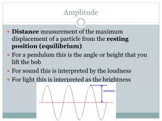
Amplitude Modulation (AM) Transmit the modulated signal with the carrier signal to simplify the complexity of the receivers. Condition for demodulation using envelope detection for all t Modulation index +
Example: Tone Modulation Sketch φAM(t) for modulation indices of µ = 0.5 and µ = 1, when m(t) = bcosωmt.
Sideband and Carrier Power carrier sidebands Power of the carrier (wasted): Power of the sidebands: Power efficiency:
Example Determine η and the percentage of the total power carried by the sidebands of the AM wave for tone modulation when (a) µ =1 (b) µ = 0.5 (c) µ = 0.3
Demodulation of AM Signals Rectifier
Demodulation of AM Signals Envelope Detector or
Bandwidth-Efficient Amplitude Modulations Single-Sideband (SSB) modulation, which remove either the LSB or the USB so that for one message signal m(t), there is only a bandwidth of B Hz. Quadrature Amplitude (QAM) modulation, which utilize spectral redundancy by sending two messages over the same of 2B Hz.
Amplitude Modulation: Single Sideband (SSB) Single-Sideband (SSB) modulation, which remove either the LSB or the USB. Hilbert transform is used to remove the LSB or USB.
Hilbert Transform h(t) H(f) mh(t) m(t) Mh(f) M(f) Hilbert Transform Hilbert transform is an ideal phase shifter that shifts the phase of every positive spectral component by –π/2.
Demodulation of SSB-SC These terms can be filtered out by using low-pass filter
Tone Modulation Example: SSB Find for the simple case of a tone modulation, that is, a modulating signal that is sinusoid m(t) = cosωmt. Also demonstrate the coherent demodulation of the SSB signal.
SSB Modulation Systems Common Methods to Generate SSB 1- Phase Shift 2- Selective-filtering 3- Weaver’s These modulation methods require that the baseband signal spectrum have little power near the origin, because ideal filters and Hilbert transformer are not realizable. Speech signal has no DC and little power near the origin. For speech recognition we can eliminate all frequency components below 300 Hz.
SSB Selective-Filtering Modulation System The signal is passed through a sharp cutoff filter to eliminate the undesired sideband. Low-pass filter to eliminate the USB spectrum, and high-pass filter to eliminate the LSB spectrum. Weaver’s method modulates the signal to a low carrier frequency first and filter out the undesired SSB, after that it modulate it again to the desired high carrier frequency.
Demodulation of SSB Signal with a Carrier Where E(t) the envelope of If A>>|m(t)| Use Taylor expansion and discard higher order
Quadrature Amplitude Modulation (QAM) It is difficult to generate accurately SSB-SC, so QAM offers an attractive alternative. QAM operates by transmitting two DSB signals via carrier of the same frequency but in phase quadrature.
Quadrature Amplitude Modulation (QAM) In-phase channel Quadraturechannel
Quadrature Amplitude Modulation (QAM) Drawback of QAM An error in the phase or the frequency of the carrier at the demodulator will result in loss and Cochannel interference. The output of the low-pass filter:
Amplitude Modulations: Vestigial Sideband (VSB) VSB signals are relatively easy to generate, and their bandwidth is typically 25% greater than that of SSB signals.
Demodulation of Vestigial Sideband (VSB) -----------> 1 Substitute equation 1 and filter out spectra at ± 2fc M |f| B
Demodulation of Vestigial Sideband (VSB) BW of signal = 6 kHz fc = 20 kHz For envelope demodulation, VSB+C require larger carrier than DSB+C but less than SSB+C.
Use of VSBin Broadcast Television TV Broadcasting • Bandwidth 4.5 MHz • Has sizable power in the low-frequency region • Envelope detector is used instead of synchronous to reduce the cost of the receiver. BW for SSB = 4.5 MHz BW for DSB = 9 MHz BW for VSB = 6 MHz
Frequency Division Multiplexing (FDM) Signal multiplexing allows the transmission of several signals on the same channel. Time Division Multiplexing (TDM): several signals time-share the same channel. Frequency Division Multiplexing (FDM): several signals share the band of a channel. Analog L-carrier hierarchy Using SSB+C
Local Carrier Synchronization It is difficult for the receiver to generate the carrier in synchronization with the received carrier because of frequency shift due to Doppler effect and phase shift due to traveling. Doppler Effect ve is the speed of receiver Time Delay Two ways to recover the incoming carrier at the receiver: - The transmitter transmits a pilot (sinusoid) signal - The receiver uses nonlinear device to generate a separate carrier component to be extracted by narrow bandpass filters.
Phase-Locked Loop and Applications (PLL) Typically used to track the phase and the frequency of the carrier component of an incoming signal. Application of PLL Synchronous demodulation Timing recovery in digital receiver Remember frequency or phase shift can be represented as phase shift:
Phase-Locked Loop and Applications (PLL) eo(t) depends on the difference between the received phase θi and the generated θo at the receiver. eo(t) will control the oscillation of the voltage controlled oscillator to phase locked with θi. Output of the multiplier Output of the loop filter Instantaneous frequency of VCO =
Carrier Acquisition in DSB-SC Signal-Squaring Method
Carrier Acquisition in DSB-SC Costas Method
NTSC Television Broadcasting System NTSC: National Television System Committee The information of the entire picture is transmitted by transmitting an electrical signal proportion to the brightness level of the pixels taken in a certain sequence. The optical system of the television camera tube generates a focused image on a photo cathode, which eventually produces electrically charged image on another surface (target mosaic). Charge Coupled Device
NTSC Television Broadcasting System NTSC: National Television System Committee More pixels High Resolution More data Few pixels LowResolution Less data
NTSC Television Broadcasting System Scanning Pattern Line scanning Frame scanning Time to scan one horizontal line: 53.5 µs Time to fly back to scan next line (blank no data): 10 µs Time to scan one frame: 15.71 ms Time to fly back to scan next frame (blank): 0.95 ms Total number of frames per second: 60 frame/sec
NTSC Television Broadcasting System Scanning Pattern white: more positive charge VSB+C DSB
NTSC Television Standard and Bandwidth 525 lines per frame 495 lines per frame are active scanning 40 frames per second needed to avoid flicker and jerky motion. 30 frames per second to conserve bandwidth in NTSC standard Frame scanned twice and in each scan only 247.5 line is used. First scan is the solid lines and the second scan is dashed lines. Bandwidth If frame consist of 525 by 525 pixels and 30 frames per second, then BW = 525 X 525 X 30 = 8.27 X 106 pixels (pulse) per second. = 4.135 MHz