Advanced MEMS Modeling Techniques for Smart System Applications
This research focuses on Microelectromechanical Systems (MEMS), which are crucial components consisting of micrometer-scale electrical and mechanical systems made through semiconductor fabrication. The study covers the manufacturing processes of MEMS, including silicon etching, and their diverse applications such as in vehicle accelerometers and portable medical devices. It also details the modeling of MEMS cantilever beams using Verilog-AMS, highlighting the comparison of single-element and multi-element models to understand their dynamic performance. The findings will inform future software tools for MEMS analysis.

Advanced MEMS Modeling Techniques for Smart System Applications
E N D
Presentation Transcript
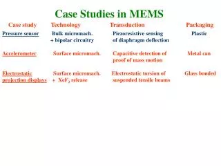
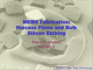
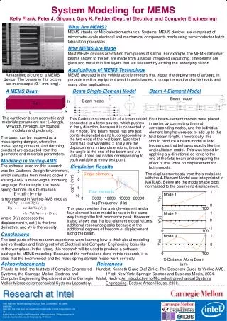
System Modeling for MEMS Kelly Frank, Peter J. Gilgunn, Gary K. Fedder (Dept. of Electrical and Computer Engineering) What Are MEMS? MEMS stands for Microelectromechanical Systems. MEMS devices are comprised of micrometer-scale electrical and mechanical components made using semiconductor batch fabrication processes. How MEMS Are Made Most MEMS devices are etched from pieces of silicon. For example, the MEMS cantilever beams shown to the left are made from a silicon integrated circuit chip. The beams are glass and metal thin film layers that are released by etching the underlying silicon. Applications of MEMS Technology MEMS are used in the vehicle accelerometers that trigger the deployment of airbags, in portable medical equipment used in ambulances, in computer read and write heads and many other applications. A magnified picture of a MEMS device. Thebeamsin this picture are microscopic (0.1 mm long). Beam Single-Element Model Beam 4-Element Model A MEMS Beam Beam model Beam model h E,ρ w L The cantilever beam geometric and materials parameters are: L=length, w=width, h=height, E=Young’s modulus and ρ=density. This Cadence schematic is of a beam model connected to a force source, which pushes in the y direction, because it is connected to the y node. The beam model has two test points designated a and b, corresponding to the two ends of the real beam. Each test point has four variables: x and y are the displacements in two dimensions, theta is the angle at the end of the beam and v is voltage. There are nodes corresponding to each variable at every test point. Four beam-element models were placed in series by connecting them at corresponding nodes, and the individual element lengths were set to add up to the total beam length. Theoretically, this should produce a beam model at low frequencies that behaves exactly like the original beam model. This was tested by applying a y-directional ac force to the end of the total beam and comparing the effect of that force on displacement for both models. The beam can be modeled as a mass-spring-damper, where the mass, spring constant, and damping constant are calculated from the geometric and materials parameters. Modeling in Verilog-AMS The software used for this research was the Cadence Design Environment, which simulates from models coded in Verilog-AMS, a mixed-signal modeling language. For example, the mass-spring-damper (m,k,b) equation is represented in Verilog-AMS codeas where D(y) accesses the displacement y, ddt() is the time derivative, and Vy is the velocity. µ Simulation Results 5 Single element The displacement data from the simulations with the 4-Element Model was interpolated in MATLAB. Below are the mode shape plots normalized to the beam end displacement. 0 log(y) (nm) -5 1 Four elements Mode 1 -10 0 5000 10000 15000 20000 log(Frequency) (Hz) 0 0 100 This graph verifies that a single-element and a four-element beam model behave in the same way through the first resonance peak. However, it also shows that the four-element model returns additional resonance peaks because of the additional degrees of freedom of displacement along the beam. 1 Mode 2 0 -1 0 100 Conclusions The best parts of this research experience were learning how to think about modeling and verification and finding out what Electrical and Computer Engineering looks like in the workplace. In the future, this research will be used to produce a software package for MEMS modeling. Because of the verifications done in this research, it is clear that the beam model and the mass-spring damper model work correctly. 1 Mode 3 0 0 100 AcknowledgementsReferences Thanks to Intel, the Institute of Complex Engineered Kundert, Kenneth S and Olaf Zinke. The Designers Guide to Verilog AMS.Systems, the Carnegie Mellon Electrical and 1st ed. New York: Springer Science and Business Media, 2004. Computer Engineering Department and the Carnegie Maluf, Nadim. An Introduction to Microelectromechanical Systems Mellon Microelectromechanical Systems Laboratory. Engineering. Boston: Artech House, 2000.