Download
1 / 32
400 likes | 1.78k Views
MEMS Technologies—Bulk Micromachining. mems tech bulk.ppt. 15 Mar 2007. MEMS Technologies for Fabrication. There are several standard methods for fabricating MEMS devices that employ many of the same methods used for microelectronics. These methods are:

E N D
MEMS Technologies—Bulk Micromachining mems tech bulk.ppt 15 Mar 2007
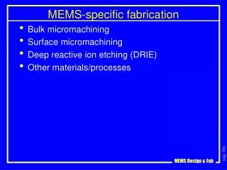
MEMS Technologies for Fabrication • There are several standard methods for fabricating MEMS devices that employ many of the same methods used for microelectronics. • These methods are: • Bulk micromachining—uses chemical etches of materials to produce articulated MEMS features that may be very thick. • Surface micromachining—uses microelectronic processes to produce thin film MEMS structures. • LIGA—a specialized method for producing very thick structures with high aspect ratios (ratio of lateral size to height).
Comparison of MEMS Technologies Here, comparisons of the 3 MEMS technologies are made relative to dimension, materials, scalability, assembly and integrability to microelectronics.
Comparison of MEMS Device Capabilities for each Technology For each MEMS technology, typical devices exhibit a range of characteristics and capabilities. These are compared in the table.
Bulk Micromachining Bulk micromachining uses both wet etch and dry etch (plasma etch) methods on single crystal silicon substrates to build elements of a MEMS micromachine or microsensor. These etch methods are similar, in some case identical, to the etch methods used to fabricate microelectronic devices. But in this case, the silicon substrate is etched to produce features in the wafer that may descend a great depth into the substrate, perhaps a the way through its thickness. Recall the character of these two etch methods. Wet etch—an etch using liquid chemicals to etch a substrate or masked pattern on a substrate; on amorphous films the etch is isotropic; on crystalline films the etch may be anisotropic. Dry etch—an etch using a plasma of ionized gaseous chemicals; the etch may exhibit either isotropic or anisotropic behavior depending on the operation of the plasma.
Isotropic versus Anisotropic Etches Some definitions: isotropic—equal in all directions anisotropic—different in different directions mask substrate or film In an isotropic etch, the chemical etches at the same rate in all directions. This can lead to mask undercutting and loss of small features. In an anisotropic etch, the chemical etches at different rates in different directions in the substrate or film.
Bulk Micromachining—Wet Etch • Indicators of a good etch process: • Critical dimension—was the correct feature size produced? • Sidewall profile—measure of the shape and angle of the sidewall. • Etch depth—how deep must the etch continue to make the feature? • Etch uniformity—measure of the etch rate across the entire wafer • Etch rate—how fast the etch proceeds; this is a through-put issue The primary materials to be etched in bulk micromachining are single-crystal Si and amorphous SiO2 or SiN (used as a masking material).
Characteristics of Wet Etches • Advantages of wet etches include: • Capable of high selectivity • Process simplicity (only have to control the chemistry) • Batch processing is possible, giving high throughput • Simpler equipment (lower cost, simpler maintenance) • Availability of crystallographic etches (ODE) • Disadvantages of wet etches • Etches are usually isotropic except for ODE, limiting small features • Surface tension of liquid chemicals (problems for small features, MEMS) • Safety (large volumes of hazardous chemicals)
Control of Wet Etches • Wet etches are controlled by a relatively small number of parameters. These include • Details of chemical composition / mixture • Temperature of the process • Agitation of the process • Cleanliness / contaminants in the solution
Composition of Typical Wet Etches • Wet etches are typically composed of several components to increase the control of the process. These parts include • oxidizing agent • oxide etchant • diluent (typically H2O) • These break the overall etch into a two-step process rather than a single step. This permits a higher degree of control of the etch by independently controlling the 2 steps. • This is seen in simple cleanup solutions like piranha: • To etch organic materials (photoresist), simple H2SO4 could be used but this creates C contaminant released into the solution. • Instead, piranha (mixture of H2SO4:H2O2:H2O) is used to produce a clean etch result.
Silicon Nitric-based Wet Etch This is an etch using HNO3:HF:CH3COOH. It can produce surfaces from a very rough etched surface to a highly polished, smooth etched surface. polishing etches in this region
Temperature Behavior of Wet Etches Chemical reactions are often critically dependent on temperature. Consider a general chemical reaction: aA + bB cC + dD The reaction rate of this (forward) reaction (ignoring chemical equilibrium) is governed by the concentration of the reactants and the temperature. reaction rate ~ [A]a[B]bexp(-Ea/kBT) k(T) concentration of B concentration of A
The Silicon Crystal Lattice The etches all depend upon chemistry, which happens through the breaking of interatomic bonds. Not surprisingly, in crystalline materials the etch rates can be different in different directions. This is the basis for crystallographic or orientational dependent etches (ODE). The Si lattice is a diamond lattice. It is composed of two interpenetrating face-centered cubic (FCC) lattices. Silicon is a group 4 element, possessing 4 valence electrons in its outermost shell. This means Si atoms will bond with four nearest-neighbors to form a crystalline solid. Directions in the Si lattice are labeled by Miller indices. The blue arrows are equivalent directions in the crystal. They are the (100) directions. Planes perpendicular are 100 planes. The red arrows, crossing a body diagonal, are the (111) directions.
Orientational Dependent Etch A standard wet etch used in bulk micromachining is a potassium hydroxide etch (KOH). KOH etches the (100) planes 100x faster than the (111) planes. As a patterned Si 100 wafer is etched by KOH, a characteristic sidewall is created at an angle of 54.7°. This can result in V-shaped grooves or trenches with positive sidewalls. (100) Si (100) wafer V-groove trench
KOH wet etch of Si (100) Bulk micromachining using KOH for a magnetic microsensor.
On a Si (110) wafer, the same KOH etch produces vertical sidewalls. Due to the chemical nature of the etch, the resulting sidewalls are extremely smooth. Si (110) wafer
100 µm KOH etch of Si 110 surface. Source: Helsinki Univ of Technology
Plasma Etch Plasma etches are also used in bulk micromachining for MEMS devices. The etch rate in a plasma etch is controlled by a number of parameters that are under control. These include Pressure Temperature (substrate and chamber) RF power (also RF frequency chosen for the process) Gas flow rate Pumping speed For example, the combination of gas flow rate into the chamber and pumping speed determine the length of time a molecule stays in the chamber. This is called residence time and it can effect the etch process at the wafer surface.
In many instances, the plasma etch rate goes through a maximum as a given control parameter is varied from a small value to a large value. In this way it is possible to optimize the etch to fit the desired needs.
The great advantage of plasma etches is that it is possible to vary the relative etch rates of the chemical etch and the physical etch due to ionic bombardment. In this manner, a variety of wall profiles may be obtained. Also, with anisotropic plasma etches it is possible to make very small features. purely chemical etch, no ion etch purely ion etch, no chemical etch combined chemical and ion etch
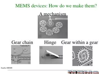
Bulk Micromachining Typical Device Features Using the methods of bulk micromachining, it is possible to manufacture a variety of mechanical structures for use in a MEMS device. cantilevers & bridges for accelerometers & articulated structures grooves & trenches for microfluidic devices. thin membranes for pressure sensors & valves
Bulk Micromachining Process Sequence The SCREAM process (single-crystal reactive etching and metallization) Isotropic plasma etch (SF6) to perform a release etch with undercutting. Perform a metal deposition (~ 0.2 µm) using sputter process for uniform thickness. Start with clean Si wafer (100) or (111). Use this sidewall mask for 2nd deep Si etch into substrate. Deposit mask oxide (PECVD SiO2, 1-2 µm) Pattern & etch the mask oxide. Deep Si etch into substrate. Strip mask oxide. Deposit a conformal oxide for sidewall masking (~ 0.3 µm). Remove the “floor” oxide using anisotropic plasma etch.
Device Example—Aerospace Corp SEM of a cantilever
![Modeling MEMS Sensors [SUGAR: A Computer Aided Design Tool for MEMS ]](https://cdn2.slideserve.com/5124381/modeling-mems-sensors-sugar-a-computer-aided-design-tool-for-mems-dt.jpg)