Download
1 / 24
260 likes | 1.13k Views
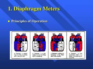
MEMS Rigid Diaphragm Speaker. Scott Maghy Tim Havard Sanchit Sehrawat. Macro-scale. Try to make MEMS device based on same concept. Motivation. Few similar products Small size Clandestine Privacy Low power Potential lower cost Highly customizable performance No surgery!.

E N D
MEMS Rigid Diaphragm Speaker Scott Maghy Tim Havard SanchitSehrawat
Macro-scale Try to make MEMS device based on same concept
Motivation • Few similar products • Small size • Clandestine • Privacy • Low power • Potential lower cost • Highly customizable performance • No surgery!
Current Hearing Devices • Few speakers that fit completely inside the ear • Some piezoelectric speakers • Bone conduction speaker for above the ear: 1 inch long • CMOS MEMS speakers exits, and are being developed • Several hearing devices • Downsides: • Require surgery • Much larger • Cost • Complexity
Implantable Hearing Devices • Cochlear Implants • Auditory Brainstem implants • Implantable Middle-ear devices • Piezoelectric devices • Electromagnetic devices
Cochlear Implants Auditory Brainstem Implants Source: http://www.nidcd.nih.gov/health/hearing/coch.asp
Piezoelectric Devices • Operation • Advantage: inert in a magnetic field • Disadvantage: Power output directly related to size of crystal. Example: • Middle Ear Transducer (MET)
Middle Ear Transducer • Translates electrical signals into mechanical motion to directly stimulate the ossicles
Middle Ear Transducer Remote MET Implant Charger
Electromagnetic Devices • Operation • Small magnet is attached to vibratory structure in ear • Only partially implantable – coil must be housed externally. Sizes of coil & magnet restricted by ear anatomy. • Power decreases as the square of the distance between coil & magnet – coil & magnet must be close
Vibrant Soundbridge Magnet surrounded by coil
Materials • Polysilicon: structural material for cantilever and diaphragm • Silicon Oxide: for sacrificial layers • Silicon Nitride: isolation of wafer • Gold: electrodes and electrical connections
Fabrication Deposit layers of Electrodes, oxide, and photoresist (as shown) Deposit Silicon Nitride Layer Pattern photoresist & then etch electrodes & oxide using RIE Deposit Oxide 2 layer
Fabrication Coat columns with Photoresist and etch away remaining oxide 2 Remove photoresist from electrode 2 Etch oxide 2, and make Poly-Si columns Deposit oxide 3 as shown Remove photoresist and deposit Poly-Si
Fabrication Make Poly-Si diaphragm base thicker Release oxide layers
Speaker Mechanics Force balance: Fspring + +/- Felect where and Setting
Acoustic Modeling Sinusoidal input voltage: Drives diaphragm displacement: Which causes sound intensity: Acoustic power can then be obtained: Note: system parameters can be tailored to be significantly below the resonant frequency.
Observed Acoustic Power • Sound intensity decays quadratically with distance This results in limited effective speaker range
Comparison of Acoustic Sound Power Decreasing frequency Device is in the threshold of human hearing!
Improvements • Implement a process that allows for sealing of speaker cone to support • This would give better acoustic properties • Could be accomplished by CMOS MEMS procedure • Fabricate cone shape with stamping method to achieve better shape and more cost effective fabrication
Improvement Cont. • Further research into materials for the cantilevers to decrease stiffness of cantilevers • This would allow greater diaphragm displacement and therefore greater intensity • Other materials exist with lower Young’s modulus that would accomplish this but fabrication is suspect • Other methods of securing the diaphragm • “Spring” attachment • Decrease the mass of the diaphragm by altering fabrication process