Download
1 / 15
150 likes | 265 Views
This document presents an in-depth review of simulation calculations for particle accelerators, focusing on the entire "start-to-end" process. It discusses the technical aspects and methodologies, including sensitivity analysis on RF parameters, mu-bunch instability, and the effects of shielding and wall conductivity. Various simulation tools such as ASTRA, ELEGANT, and GENESIS are utilized for detailed modeling. The report highlights significant findings on beam loading, stability, and phase space manipulation, providing critical insights for optimizing accelerator performance and understanding beam dynamics.

E N D
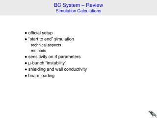
BC System – Review Simulation Calculations ● official setup ● “start to end” simulation technical aspects methods ● sensitivity on rf parameters ● µ-bunch “instability” ● shielding and wall conductivity ● beam loading
official setup Winni’s EXCEL table (Dec 2005) Klaus’s gun & ACC0 settings: 1nC, 50A slice 0.58 µm (used for s2e simulations) • 6.9 MeV • 130 MeV, dog leg, laser heater • 500 MeV, 3r harm. rf, 50A 1kA, r56 103 mm • 2 GeV, on crest, 1kA 5kA, r56 14 (17) mm 17.5 MeV
“start to end” simulation methods ASTRA, (ELEGANT,) CSRtrack, GENESIS tools format conversion, some phase space manipulations, semi-analytic space charge impedance longitudinal predictor (~ LiTrack) tuning longitudinal: rf phases to 0.01 deg, amplitudes to 0.01% semi-analytic space charge impedance steering & matching (at some locations) transverse: additional 180 deg phase advance before BC2 tricks 200000 particles details see FLS2006: http://adweb.desy.de/mpy/FLS2006/proceedings/TALKS/WG314_TALK.PDF
rf-field cavity wake & s.c. field method 1 (fast) transport matrix GENESIS ASTRA CSRtrack 1d 8 h 20 min 30 min 30 min sec…min (steady state) PC (Pentium 4, 3GHz) method 2 (reference) ASTRA CSRtrack sub-bunch ELEGANT GENESIS & sc wake 1.5 h 2 h 30 h 4 h 12 h 3 h h…w (SASE) LINUX cluster with 20 cpus (64 bit)
method 1 method 2 current & slice emittance
method 1 method 2 long. phase space
0.016 deg 0.043 deg +10% 170 kV 92 kV sensitivity on rf parameters peak current after BC2 E1/MeV = 500 L1: phi1st/deg = 2.016 V3rd /MV = 91.62 phi3rd/deg = 146.56 E2/MeV = 2000 L2: on crest r56_BC1/mm = 103.26 r56_BC2/mm = 14.060 phase of LINAC2: 2.7 deg amplitude of LINAC2: 18.5 MV r56 of BC1: 0.1% r56 of BC2: 2.4% bunch charge, Igun = const: 5.3% bunch charge, shape = const: 5.7% Igun, bunch charge = const: 2.9% with cavity wakes and injector SC effects
/ fsec V3rd = 92MV E1/MeV = 500 L1: phi1st/deg = 2.016 V3rd /MV = 91.62 phi3rd/deg = 146.56 E2/MeV = 2000 L2: on crest r56_BC1/mm = 103.26 r56_BC2/mm = 17.41 peak current after BC2 arrival time jitter without cavity wakes and injector SC effects
gain = 10 10 % current current reduced gain 1 % 1 % z z impedance impedance energy spread energy energy r56 r56 µ-bunch “instability” (SC,CSR) increase uncorrelated energy spread: ‘laser heater’
slice energy distribution P(E) rms = 2 keV (Gaussian) rms = 10 keV (from laser heater) rms = 10 keV (Gaussian) ‘laser heater’ (LCLS layout)
after dogleg after BC2 after BC1 gain curves TDR: gaussian distribution rms = 10 keV “real” heater: rms = 10keV shot noise “real” heater: dogleg, r56 = 0.84mm 0 TDR:
after dogleg after BC2 after BC1 5% current / A energy / eV cathode 0.5% after 45m (130 MeV) ~2keV s / mm energy to current modulation: TDR: gaussian distribution rms = 10 keV “real” heater: rms = 10keV ASTRA simulation: 5% modulation at cathode, = 0.2 mm injector dogleg (~45m after cathode):
gap (mm) peak current (kA) emittance norm., hor. (µm) material projected PEC 8 5.4 1.4 steel 8 12.5 8.5 cu 8 5.9 2.5 cu 10 5.8 2.2 cu 16 5.7 1.7 cu 20 5.6 1.5 1.16 (3) 5.18 3d csr & ast. 5.3 1.5 shielding and wall conductivity (same rf settings for all calculations) (same orientation of both chicanes) steady state r-wall-wake; see: http://www.desy.de/xfel-beam/data/talks/talks/dohlus_-_rwall_wake_xfel_20060206.pdf
n beam loading “short” range long range single- & multi-bunch interaction: systematic & random charge “centroid wakes” bunch energy (centroid) systematic & random part about beam loading; see: http://www.desy.de/~dohlus/2006.03.psi/beam_loading_02.pdf http://www.desy.de/xfel-beam/data/talks/talks/dohlus_-_beam_loading_20060327.pdf
beam loading: some conclusions systematic beam loading is important comes always to steady state transients not investigated now; (some unknown parameters) random beam loading (by charge fluctuation) main modes: feed back required significant contribution from 3rd harmonic rf transverse deflecting cavities are not considered now self interaction self & multi-bunch interaction; (unknown parameters estimated)