Combinational Logic Analysis
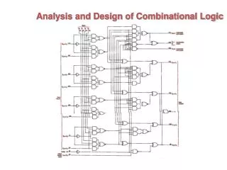
Combinational Logic Analysis. AB. A. B. X=AB+CD. C. D. CD. Basic Combinational Logic Circuits. AND-OR logic AND-OR logic produces an SOP expression. In general, an AND-OR circuit can have any number of AND gates each with any number of inputs. SOP. AB. A. B. X=AB+CD. C. D. CD.

Combinational Logic Analysis
E N D
Presentation Transcript
AB A B X=AB+CD C D CD Basic Combinational Logic Circuits • AND-OR logic • AND-OR logic produces an SOP expression. • In general, an AND-OR circuit can have any number of AND gates each with any number of inputs. SOP
AB A B X=AB+CD C D CD Basic Combinational Logic Circuits
AB A B X=AB+CD C AB+CD POS D CD Basic Combinational Logic Circuits • AND-OR-Invert logic
A B Basic Combinational Logic Circuits • Exclusive-OR logic XOR
A XOR B X A X B Basic Combinational Logic Circuits • Exclusive-NOR logic
Implementing Combinational Logic • Boolean expression logic circuit • For every Boolean expression there is a logic circuit, and for every logic circuit there is a Boolean expression What’s the benefit? >> Less overall propagation delay <<
Implementing Combinational Logic • Truth table logic circuit • If you begin with a truth table of an expression, you can write the SOP expression from the truth table and then implement the logic circuit. • Remember? SOP AND-OR implementation.
Universal Gates • The NAND gate
Universal Gates • The NOR gate
Logic Circuit Operation with Pulse • How can we deal with combinational logic circuits with pulse waveform inputs? • The operation of each gate is the same for pulse waveform inputs as for constant-level inputs. • The output of a logic circuit at any given time depends on the inputs at that particular time, so the relationship of the time-varying inputs is of primary importance.
Logic Circuit Operation with Pulse • Let’s get to the basic with a given individual gate: