Download
1 / 23
240 likes | 433 Views
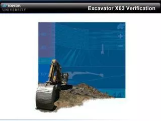
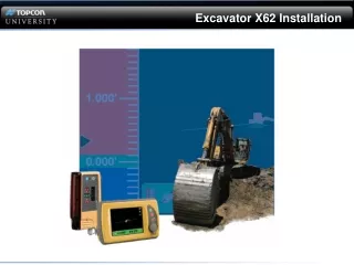
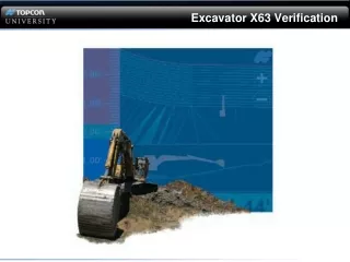
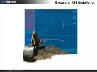
Excavator X63 Installation. Reference Materials. Reference Materials. 7010-0696. 7010-0697. Theory of Operation. Main Antenna Left (GPS Position) Implement lengths Angles between implement Aux Antenna Right (Heading). Theory of Operation. TS-1 sensors measure implement angle.

E N D
Reference Materials • Reference Materials 7010-0696 7010-0697
Theory of Operation • Main Antenna Left (GPS Position) • Implement lengths • Angles between implement • Aux Antenna Right (Heading)
Theory of Operation • TS-1 sensors measure implement angle
Component Overview GX60
GX60 • Features • Operating Sys • Windows XP • Touch Screen Display • 640X840 • USB Port • Data Transfer • Ram or Jaw Mounting
MC-R3/2.5 • Configured for Dual GPS MC 2.5 Current MC-R3 (Soon to be released)
MC-A1 AUX Antenna (Heading) Main Antenna (Position)
TS-1 Overview • 3-Axis 3600 sensor • Mounting any orientation • Parallel to axis being measured
TS-1 Options Body Boom Stick Bucket *Tilt Bucket *Split Boom/Add a Stick *Optional sensors
TS-1 Sensor Arrow Orientation • Orientation (Arrow on sensor) • Parallel to axis being measured
Cabling Restrictions • Bending Radius 3”/8cm • Start at the Bucket Sensor to prevent excess cable
Bucket Sensor Installation • Bucket 0o • Sensor parallel with stick-to-bucket centerline • +/- 20o of pivot centerline
Dog Bone Installation • Additional Protection • Additional Calibration steps
Tilt Bucket Sensor Installation Tile Bucket Mounting (Optional)
Bucket Sensor Cover Sensor Covers & cable protection
Stick Sensor Installation • Parallel to the stick-to-bucket centerline. • +/- 20o of the pivot centerline.
Boom Sensor Installation • Parallel to the Boom centerline. • +/- 20o of the pivot centerline.
Body Sensor Installation • Parallel to the Boom pivot • +/- 20o of Track Centerline