Chapter 4 Transients
Chapter 4 Transients. Chapter 4 Transients. Solve first-order RC or RL circuits. 2 . Understand the concepts of transient response and steady-state response. 3 . Relate the transient response of first-order circuits to the time constant.


Chapter 4 Transients
E N D
Presentation Transcript
Chapter 4Transients • Solve first-order RC or RL circuits. • 2. Understand the concepts of transient response and steady-state response.
3. Relate the transient response of first-order circuits to the time constant. 4. Solve RLC circuits in dc steady-state conditions. 5. Solve second-order circuits. 6. Relate the step response of a second-order system to its natural frequency and damping ratio.
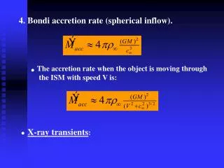
Transients The time-varying currents and voltages resulting from the sudden application of sources, usually due to switching, are called transients. By writing circuit equations, we obtain integrodifferential equations.
The time interval τ = RC iscalled the time constant ofthe circuit.
DC STEADY STATE The steps in determining the forced response for RLC circuits with dc sources are: 1. Replace capacitances with open circuits. 2. Replace inductances with short circuits. 3. Solve the remaining circuit.
RL CIRCUITS The steps involved in solving simple circuits containing dc sources, resistances, and one energy-storage element (inductance or capacitance) are:
1. Apply Kirchhoff’s current and voltage laws to write the circuit equation.2. If the equation contains integrals, differentiate each term in the equation to produce a pure differential equation.3. Assume a solution of the form K1+ K2est.
4. Substitute the solution into the differential equation to determine the values of K1 and s . (Alternatively, we can determine K1 by solving the circuit in steady state as discussed in Section 4.2.)5. Use the initial conditions to determine the value of K2.6. Write the final solution.
RL Transient Analysis Time constant is
RC AND RL CIRCUITS WITH GENERAL SOURCES The general solution consists of two parts.
The particular solution (also called the forced response) is any expression that satisfies the equation. In order to have a solution that satisfies the initial conditions, we must add the complementary solution to the particular solution.
The homogeneous equation is obtained by setting the forcing function to zero. The complementary solution (also called the natural response) is obtained by solving the homogeneous equation.
Step-by-Step Solution Circuits containing a resistance, a source, and an inductance (or a capacitance) 1. Write the circuit equation and reduce it to a first-order differential equation.
2. Find a particular solution. The details of this step depend on the form of the forcing function. We illustrate several types of forcing functions in examples, exercises, and problems. 3. Obtain the complete solution by adding the particular solution to the complementary solution given by Equation 4.44, which contains the arbitrary constant K. 4. Use initial conditions to find the value of K.
1. Overdamped case (ζ > 1). If ζ > 1 (or equivalently, if α > ω0), the roots of the characteristic equation are real and distinct. Then the complementary solution is In this case, we say that the circuit is overdamped.
2. Critically damped case (ζ = 1). If ζ = 1 (or equivalently, if α = ω0 ), the roots are real and equal. Then the complementary solution is In this case, we say that the circuit is critically damped.
3. Underdamped case (ζ < 1). Finally, if ζ < 1 (or equivalently, if α < ω0), the roots are complex. (By the term complex, we mean that the roots involve the square root of –1.) In other words, the roots are of the form in which j is the square root of -1 and the natural frequency is given by
In electrical engineering, we use j rather than i to stand for square root of -1, because we use i for current. For complex roots, the complementary solution is of the form In this case, we say that the circuit is underdamped.