Download
1 / 105
1.06k likes | 1.27k Views
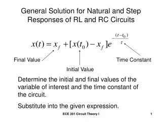
Transients and Step Responses. ELCT222- Lecture Notes University of S. Carolina Fall2011. Outline. RC transients charging RC transients discharge RC transients Thevenin P-SPICE RL transients charging RL transients discharge Step responses. P-SPICE simulations Applications. Reading:

E N D
Transients and Step Responses ELCT222- Lecture Notes University of S. Carolina Fall2011
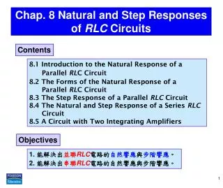
Outline • RC transients charging • RC transients discharge • RC transients Thevenin • P-SPICE • RL transients charging • RL transients discharge • Step responses. • P-SPICE simulations • Applications Reading: Boylestad Sections 10.5, 10.6, 10.7, 10.9,10.10 24.1-24.7
FIG. 10.26 Basic R-C charging network. TRANSIENTS IN CAPACITIVE NETWORKS: THE CHARGING PHASE • The placement of charge on the plates of a capacitor does not occur instantaneously. • Instead, it occurs over a period of time determined by the components of the network.
FIG. 10.27 vC during the charging phase. TRANSIENTS IN CAPACITIVE NETWORKS: THE CHARGING PHASE
FIG. 10.28 Universal time constant chart. TRANSIENTS IN CAPACITIVE NETWORKS: THE CHARGING PHASE
TABLE 10.3 Selected values of e-x. TRANSIENTS IN CAPACITIVE NETWORKS: THE CHARGING PHASE
TRANSIENTS IN CAPACITIVE NETWORKS: THE CHARGING PHASE • The factor t, called the time constant of the network, has the units of time, as shown below using some of the basic equations introduced earlier in this text: The larger R is, the lower the charging current, longer time to charge The larger C is, the more charge required for a given V, longer time.
FIG. 10.29 Plotting the equation yC =E(1 –e-t/t) versus time (t). TRANSIENTS IN CAPACITIVE NETWORKS: THE CHARGING PHASE
FIG. 10.32 Revealing the short-circuit equivalent for the capacitor that occurs when the switch is first closed. TRANSIENTS IN CAPACITIVE NETWORKS: THE CHARGING PHASE
FIG. 10.31 Demonstrating that a capacitor has the characteristics of an open circuit after the charging phase has passed. TRANSIENTS IN CAPACITIVE NETWORKS: THE CHARGING PHASE
FIG. 10.34 Calculator key strokes to determine e-1.2. TRANSIENTS IN CAPACITIVE NETWORKS: THE CHARGING PHASEUsing the Calculator to Solve Exponential Functions
FIG. 10.35 Transient network for Example 10.6. TRANSIENTS IN CAPACITIVE NETWORKS: THE CHARGING PHASEUsing the Calculator to Solve Exponential Functions
FIG. 10.36 vC versus time for the charging network in Fig. 10.35. TRANSIENTS IN CAPACITIVE NETWORKS: THE CHARGING PHASEUsing the Calculator to Solve Exponential Functions
FIG. 10.37 Plotting the waveform in Fig. 10.36 versus time (t). TRANSIENTS IN CAPACITIVE NETWORKS: THE CHARGING PHASEUsing the Calculator to Solve Exponential Functions
FIG. 10.38 iC and yR for the charging network in Fig. 10.36. TRANSIENTS IN CAPACITIVE NETWORKS: THE CHARGING PHASEUsing the Calculator to Solve Exponential Functions
TRANSIENTS IN CAPACITIVE NETWORKS: THE DISCHARGING PHASE • We now investigate how to discharge a capacitor while exerting some control on how long the discharge time will be. • You can, of course, place a lead directly across a capacitor to discharge it very quickly—and possibly cause a visible spark. • For larger capacitors such those in TV sets, this procedure should not be attempted because of the high voltages involved—unless, of course, you are trained in the maneuver.
FIG. 10.39 (a) Charging network; (b) discharging configuration. TRANSIENTS IN CAPACITIVE NETWORKS: THE DISCHARGING PHASE
TRANSIENTS IN CAPACITIVE NETWORKS: THE DISCHARGING PHASE • For the voltage across the capacitor that is decreasing with time, the mathematical expression is:
FIG. 10.40 yC, iC, and yR for 5t switching between contacts in Fig. 10.39(a). TRANSIENTS IN CAPACITIVE NETWORKS: THE DISCHARGING PHASE
FIG. 10.41 vC and iC for the network in Fig. 10.39(a) with the values in Example 10.6. TRANSIENTS IN CAPACITIVE NETWORKS: THE DISCHARGING PHASE
TRANSIENTS IN CAPACITIVE NETWORKS: THE DISCHARGING PHASEThe Effect of on the Response
FIG. 10.43 Effect of increasing values of C (with R constant) on the charging curve for vC. TRANSIENTS IN CAPACITIVE NETWORKS: THE DISCHARGING PHASEThe Effect of on the Response
FIG. 10.44 Network to be analyzed in Example 10.8. TRANSIENTS IN CAPACITIVE NETWORKS: THE DISCHARGING PHASEThe Effect of on the Response
FIG. 10.45 vC and iC for the network in Fig. 10.44. TRANSIENTS IN CAPACITIVE NETWORKS: THE DISCHARGING PHASEThe Effect of on the Response
FIG. 10.46 Network to be analyzed in Example 10.9. FIG. 10.47 The charging phase for the network in Fig. 10.46. TRANSIENTS IN CAPACITIVE NETWORKS: THE DISCHARGING PHASEThe Effect of on the Response
FIG. 10.48 Network in Fig. 10.47 when the switch is moved to position 2 at t =1t1. TRANSIENTS IN CAPACITIVE NETWORKS: THE DISCHARGING PHASEThe Effect of on the Response
FIG. 10.49 vC for the network in Fig. 10.47. TRANSIENTS IN CAPACITIVE NETWORKS: THE DISCHARGING PHASEThe Effect of on the Response
FIG. 10.50 ic for the network in Fig. 10.47. TRANSIENTS IN CAPACITIVE NETWORKS: THE DISCHARGING PHASEThe Effect of on the Response
FIG. 10.51 Defining the regions associated with a transient response. INITIAL CONDITIONS • The voltage across the capacitor at this instant is called the initial value, as shown for the general waveform in Fig. 10.51.
FIG. 10.52 Example 10.10. INITIAL CONDITIONS
FIG. 10.53 vC and iC for the network in Fig. 10.52. INITIAL CONDITIONS
FIG. 10.54 Defining the parameters in Eq. (10.21) for the discharge phase. INITIAL CONDITIONS
FIG. 10.55 Key strokes to determine (2 ms)(loge2) using the TI-89 calculator. INSTANTANEOUS VALUES • Occasionally, you may need to determine the voltage or current at a particular instant of time that is not an integral multiple of t.
THÉVENIN EQUIVALENT: t =RThC • You may encounter instances in which the network does not have the simple series form in Fig. 10.26. • You then need to find the Thévenin equivalent circuit for the network external to the capacitive element.
FIG. 10.56 Example 10.11. THÉVENIN EQUIVALENT: t =RThC
FIG. 10.57 Applying Thévenin’s theorem to the network in Fig. 10.56. THÉVENIN EQUIVALENT: t =RThC
FIG. 10.58 Substituting the Thévenin equivalent for the network in Fig. 10.56. THÉVENIN EQUIVALENT: t =RThC
FIG. 10.59 The resulting waveforms for the network in Fig. 10.56. THÉVENIN EQUIVALENT: t =RThC
FIG. 10.61 Network in Fig. 10.60 redrawn. FIG. 10.60 Example 10.12. THÉVENIN EQUIVALENT: t =RThC
FIG. 10.62 yC for the network in Fig. 10.60. THÉVENIN EQUIVALENT: t =RThC
FIG. 10.63 Example 10.13. THÉVENIN EQUIVALENT: t =RThC
THE CURRENT iC • There is a very special relationship between the current of a capacitor and the voltage across it. • For the resistor, it is defined by Ohm’s law: iR = vR/R. • The current through and the voltage across the resistor are related by a constant R—a very simple direct linear relationship. • For the capacitor, it is the more complex relationship defined by:
FIG. 10.64 vC for Example 10.14. THE CURRENT iC
FIG. 10.65 The resulting current iC for the applied voltage in Fig. 10.64. THE CURRENT iC
R-L TRANSIENTS: THE STORAGE PHASE • The storage waveforms have the same shape, and time constants are defined for each configuration. • Because these concepts are so similar (refer to Section 10.5 on the charging of a capacitor), you have an opportunity to reinforce concepts introduced earlier and still learn more about the behavior of inductive elements.
FIG. 11.31 Basic R-L transient network. R-L TRANSIENTS: THE STORAGE PHASE Remember, for an inductor
FIG. 11.32 iL, yL, and yR for the circuit in Fig. 11.31 following the closing of the switch. R-L TRANSIENTS: THE STORAGE PHASE